Measured-Signal Repetition Frequency Detection Method, and Sampling Apparatus and Waveform Observation System Using the Method
- Summary
- Abstract
- Description
- Claims
- Application Information
AI Technical Summary
Benefits of technology
Problems solved by technology
Method used
Image
Examples
first embodiment
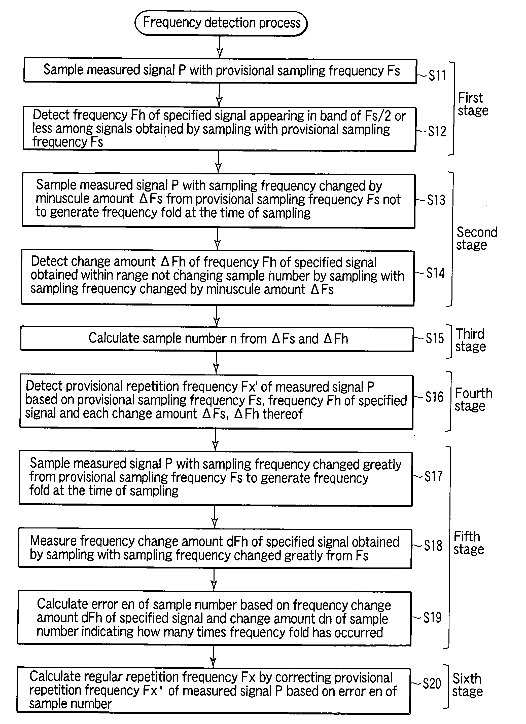
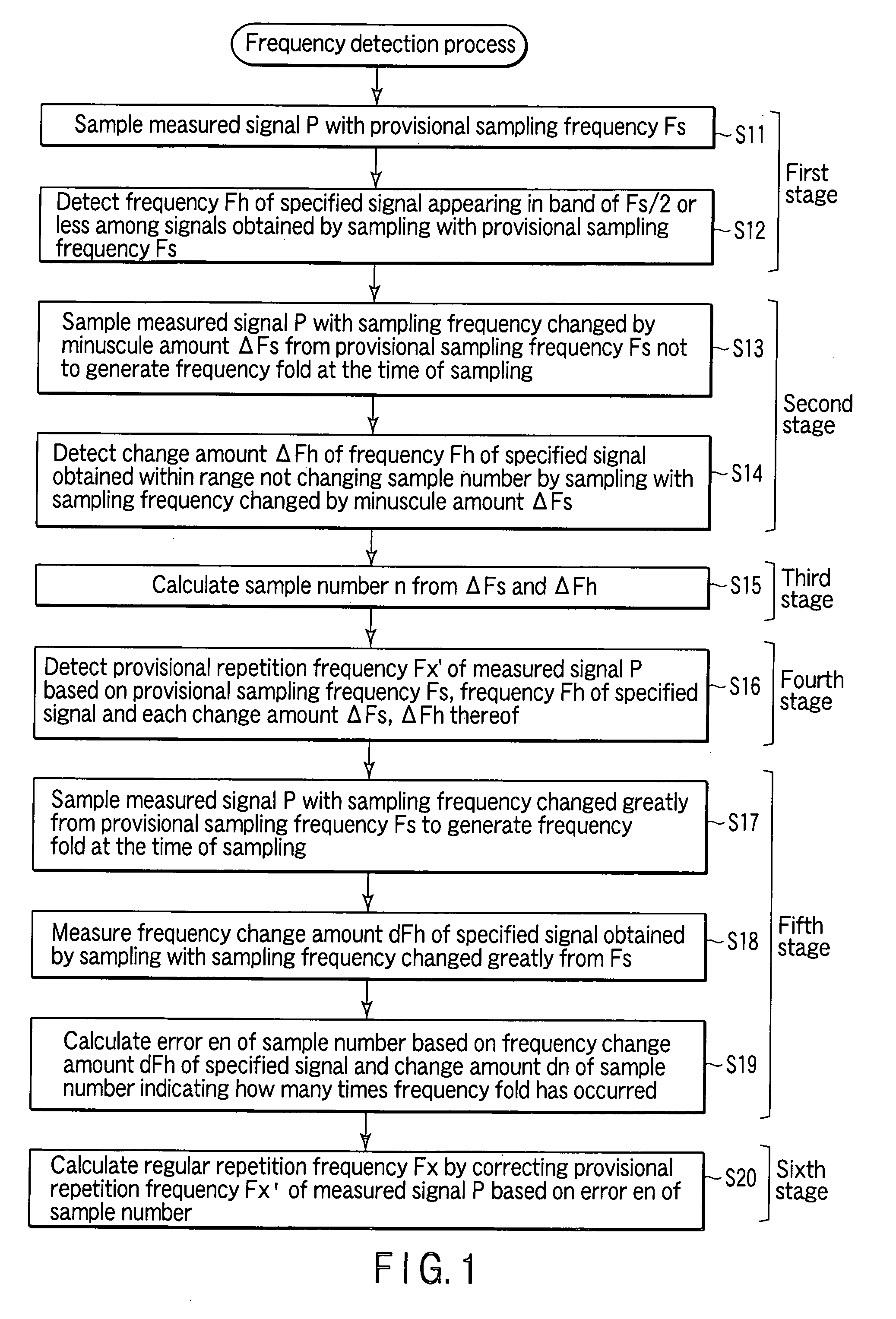
[0196]FIG. 1 is a flowchart shown for explaining the steps of a measured-signal repetition frequency detection method according to a first embodiment of the invention.
[0197]The measured-signal repetition frequency detection method according to the invention basically is characterized by including a first stage (S11, S12) for detecting a frequency Fh of a specified signal appearing in the band not more than one half of a provisional sampling frequency Fs among the signals obtained by sampling the measured signal with the provisional sampling frequency Fs; a second stage (S13, S14) for calculating a frequency change amount ΔFh of the specified signal obtained by the sampling frequency changed from the provisional sampling frequency Fs by a minuscule frequency ΔFs not generating a frequency fold at the time of sampling; a third stage (S15) for calculating a sample number n from Equation (1):
n=ΔFh / ΔFs (1)
having the denominator equal to the minuscule frequency ΔFs in the second stage (S...
second embodiment
[0228]FIG. 4 is a block diagram shown for explaining the configuration of a waveform observation system including a measured-signal sampling apparatus according to a second embodiment of the invention.
[0229]This waveform observation system 20 according to the second embodiment, like the waveform observation system 20 including the measured-signal sampling apparatus similar to the Japanese prior application filed by the present inventor shown in FIG. 15, in order to execute steps S11 to S14 and S16 of the measured-signal repetition frequency detection method according to the first embodiment described above, specifically includes, as shown in FIG. 4, a parameter designation unit 22, an arithmetic unit 23, a signal generating unit 24, a sampling pulse generating unit 25, an optical sampling unit 26, a specified signal frequency detector 27 and a provisional repetition frequency calculation unit (in FIG. 15, the repetition frequency calculation unit) 28.
[0230]Also, the waveform observa...
third embodiment
[0272]FIG. 9 is a block diagram shown for explaining the configuration of a waveform observation system including a measured-signal sampling apparatus according to a third embodiment of the invention.
[0273]A waveform observation system 40 including the measured-signal sampling apparatus according to the third embodiment has such a configuration that the sampling apparatus 21 included in the waveform observation system 20 according to the second embodiment and the function of the digital oscilloscope 60 are accommodated in the same housing and integrated with each other.
[0274]Specifically, the waveform observation system 40 including the measured-signal sampling apparatus according to the third embodiment includes, in addition to each component element of the sampling apparatus 21 shown in FIG. 4 above, an A / D converter 43, a data acquisition control unit 44, a waveform data memory 45, a display control unit 46, a display unit 47 and an observation mode designation unit 48.
[0275]The ...
PUM
 Abstract
Description
Claims
Application Information
 - R&D
- Intellectual Property
- Life Sciences
- Materials
- Tech Scout
- Unparalleled Data Quality
- Higher Quality Content
- 60% Fewer Hallucinations
Browse by: Latest US Patents, China's latest patents, Technical Efficacy Thesaurus, Application Domain, Technology Topic, Popular Technical Reports.
© 2025 PatSnap. All rights reserved.Legal|Privacy policy|Modern Slavery Act Transparency Statement|Sitemap|About US| Contact US: help@patsnap.com


