Signal processing device using magnetic film and signal processing method

a technology of signal processing and magnetic film, which is applied in the direction of magnetic variable regulation, pulse technique, instruments, etc., can solve the problems of the physical limit approaching, and the power consumption of the device becoming a major problem

Active Publication Date: 2010-09-09
KIOXIA CORP
View PDF6 Cites 17 Cited by
  • Summary
  • Abstract
  • Description
  • Claims
  • Application Information

AI Technical Summary

Problems solved by technology

It is expected, however, that the miniaturization, which has been promoted so far by solving a multitude of manufacturing problems, will eventually reach the physical limit.
In addition, along with the miniaturization, power consumption of the devices has become a major problem.
This has led to skyrocketing power consumption along with t

Method used


Image

  • Signal processing device using magnetic film and signal processing method
  • Signal processing device using magnetic film and signal processing method
  • Signal processing device using magnetic film and signal processing method

Examples


first embodiment

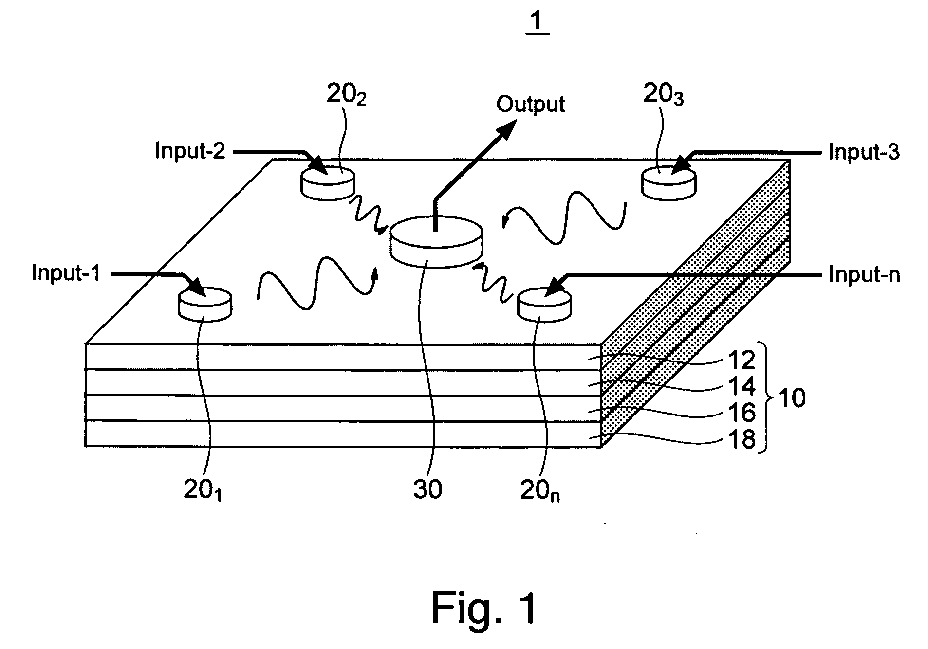
[0030]FIG. 1 shows a basic structure of a signal processing device according to a first embodiment of the present invention. The signal processing device 1 includes a continuous film 10 which is provided on a substrate (not shown) and which contains at least one magnetic layer exhibiting ferromagnetism at room temperature, multiple spin wave generators 201 to 20n which are provided on the continuous film 10 via a contact surface, and at least one signal detection electrode (signal detector) 30. Alternatively, the drawing of FIG. 1 may be turned upside down. That is, the substrate may be disposed on the spin wave generators 201 to 20n and the at least one signal detection electrode (signal detector) 30, or under the continuous film 10.

[0031]Each spin wave generator 20i (i=1 to n) is provided on the continuous film 10 via a dot-shaped contact surface, and capable of generating spin waves in a region of the magnetic layer constituting the continuous film 10, which is immediately under ...

second embodiment

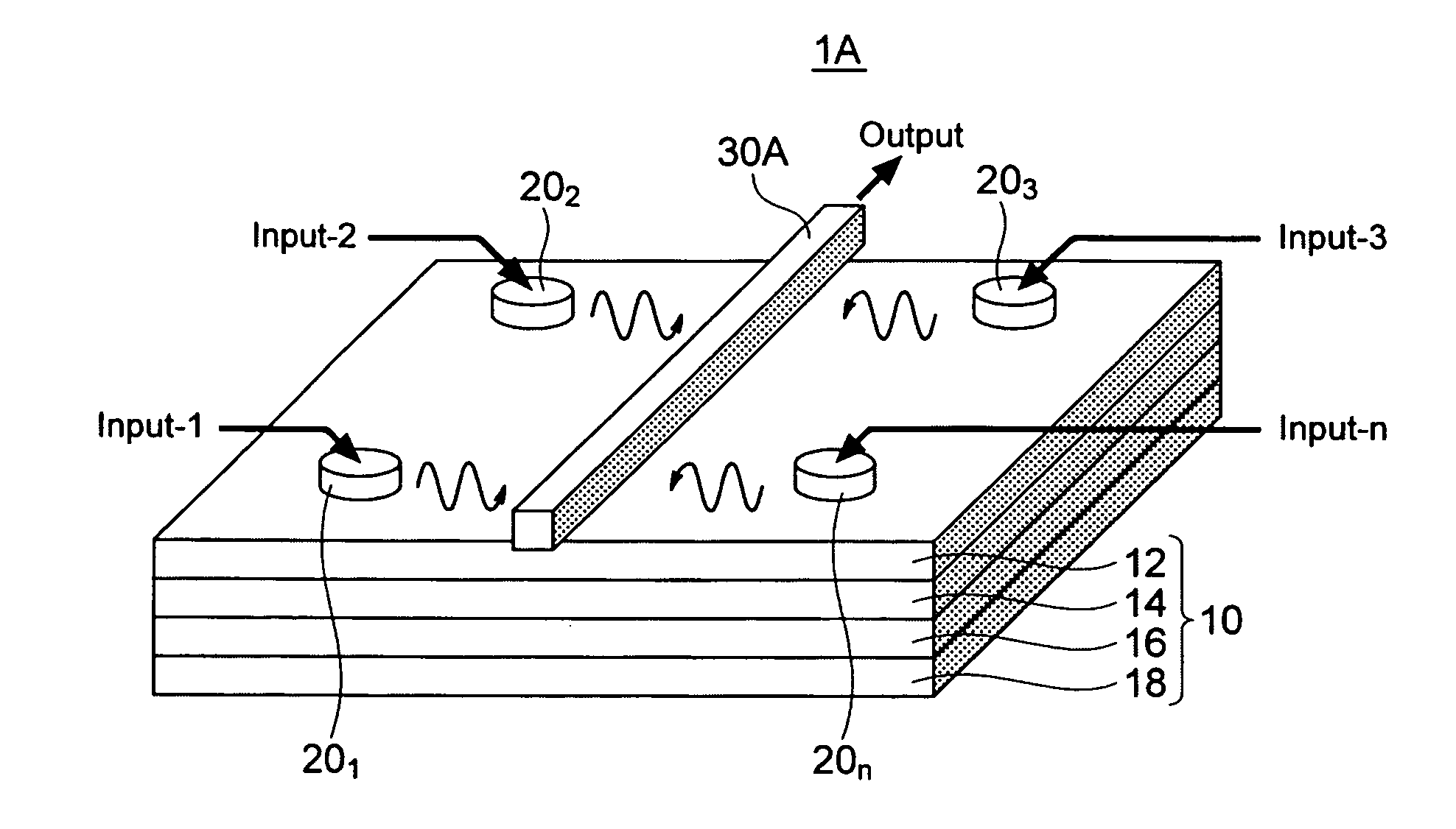
[0057]Next, a signal processing device according to a second embodiment of the invention is shown in FIG. 11. The signal processing device 1A of the embodiment is different from the signal processing device of the first embodiment shown in FIG. 1 in that the signal detection electrode 30 is replaced by a signal detection electrode 30A. The signal processing device 1A of the second embodiment corresponds to the signal processing device of the first embodiment shown in FIG. 1 whose signal detection electrode 30 is replaced by a signal detection electrode 30A. The signal detection electrode 30A has an elongate line shaped contact surface in contact with the continuous film 10, and includes a conducting material. When a magnetic layer of the continuous film 10 includes a metal, the signal processing device 1A has an insulation layer (not shown) between the signal detection electrode 30A and the magnetic layer of the continuous film 10. Although the signal detection electrode 30A include...

first example

[0063]A first example of the invention will be described hereinafter with reference to FIG. 13. The first example is a signal processing device of the first and second embodiments, which is provided with two spin wave generators 201, 202 on the continuous film 10 and the signal detection electrode 30 in the center as shown in FIG. 13. Results of experiments on a positional relationship between the spin wave generators 201, 202 and the signal detection electrode 30 in the first example are described. Here, each contact surface of the spin wave generators 201, 202 in contact with the continuous film and a contact surface of the signal detection electrode 30 in contact with the continuous film are circles whose diameters of the contact surfaces are 50 nmφ and 300 nmφ, respectively. Test samples S1 to S6 with respective six combinations of distances d1, d2, which are different from each other as shown in Table 1, are provided. Here, the distances d1, d2, are each a distance from the res...


PUM


Abstract

A signal processing device includes a continuous film, a plurality of spin wave generators, and at least one signal detector. The continuous film includes at least one magnetic layer. The plurality of spin wave generators are provided on the continuous film in such a manner as to be in direct contact with the continuous film or be in contact with the continuous film while having an insulation layer interposed therebetween, and each has a contact surface with the continuous film in a dot shape and generates a spin wave in a region of the magnetic layer of the continuous film by receiving an input signal, the region being immediately under the contact surface. The signal detector is provided on the continuous film and detects, as an electrical signal, the spin waves generated by the spin wave generators and propagating through the continuous film.

Description

CROSS REFERENCE TO RELATED APPLICATION[0001]This application is based upon and claims the benefit of priority from the prior Japanese Patent Application No. 2009-050543, filed on Mar. 4, 2009, the entire contents of which are incorporated herein by reference.FIELD OF THE INVENTION[0002]The present invention relates to a signal processing device using a magnetic film and a signal processing method.DESCRIPTION OF THE BACKGROUND[0003]Miniaturization of CMOS devices has led to improved performance of a signal processing device. The device, as a logic processing unit, has contributed to higher functions and higher performances of products in various markets. It is expected, however, that the miniaturization, which has been promoted so far by solving a multitude of manufacturing problems, will eventually reach the physical limit. In addition, along with the miniaturization, power consumption of the devices has become a major problem. Dynamic power increasing with the miniaturization has b...

Claims


Application Information

Patent Timeline
IPC IPC(8): G01R33/28
CPCH03K19/18H01L43/08H10N50/10
Inventor NAKAMURA, SHIHOMORISE, HIROFUMI
Owner KIOXIA CORP
Why Eureka
Try Eureka