
Mapping for MIMO Communication Apparatus

a communication apparatus and mimo technology, applied in the field of mapping signals, can solve the problems of inability to implement a practical system, inability to use multiple streams, prohibitively complicated ml demodulation schemes,

Inactive Publication Date: 2010-09-09
MITSUBISHI ELECTRIC RES LAB INC
View PDF2 Cites 37 Cited by
  • Summary
  • Abstract
  • Description
  • Claims
  • Application Information

AI Technical Summary

Problems solved by technology

This makes the ML demodulation scheme prohibitively complicated and thus infeasible for practical system implementation.
It is noted that in such receivers, the multiple streams interfere with each other.
This lack of change of the matrix P leads to a performance loss when linear receivers are used.
Due to the channel realization, if one of the estimated spatial streams has a very low SINR, there is no mechanism available for the conventional scheme with a fixed matrix P to improve its SINR.
However, for relatively low Doppler frequencies, this is not a feasible option due to the long codeword lengths required.
This makes it hard for the channel decoder to recover the original information bits.
An almost static channel and the unavailability of time domain diversity within each frame, thus leads to higher frame error rates in the conventional scheme.

Method used


Image

  • Mapping for MIMO Communication Apparatus
  • Mapping for MIMO Communication Apparatus
  • Mapping for MIMO Communication Apparatus

Examples


examples

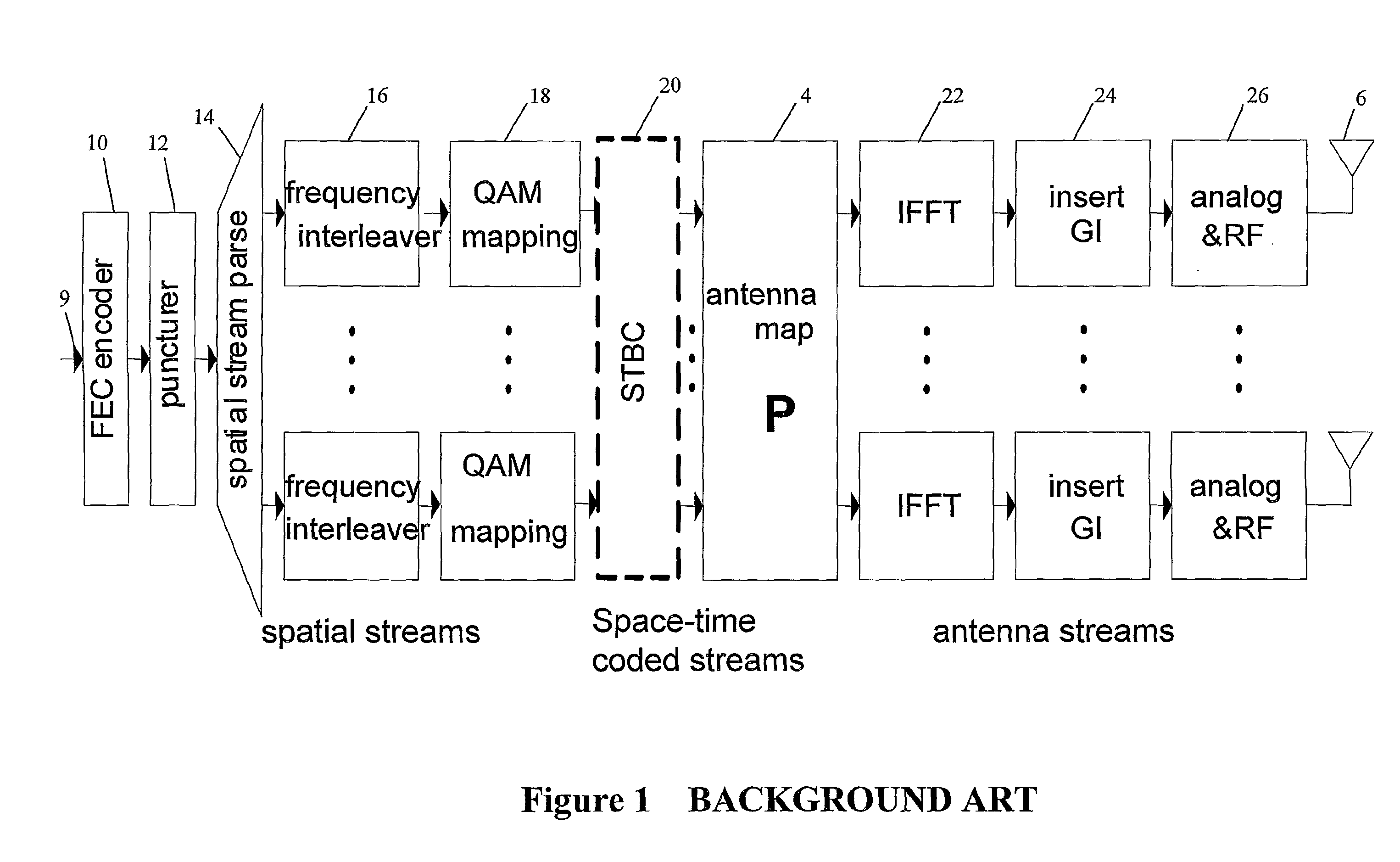
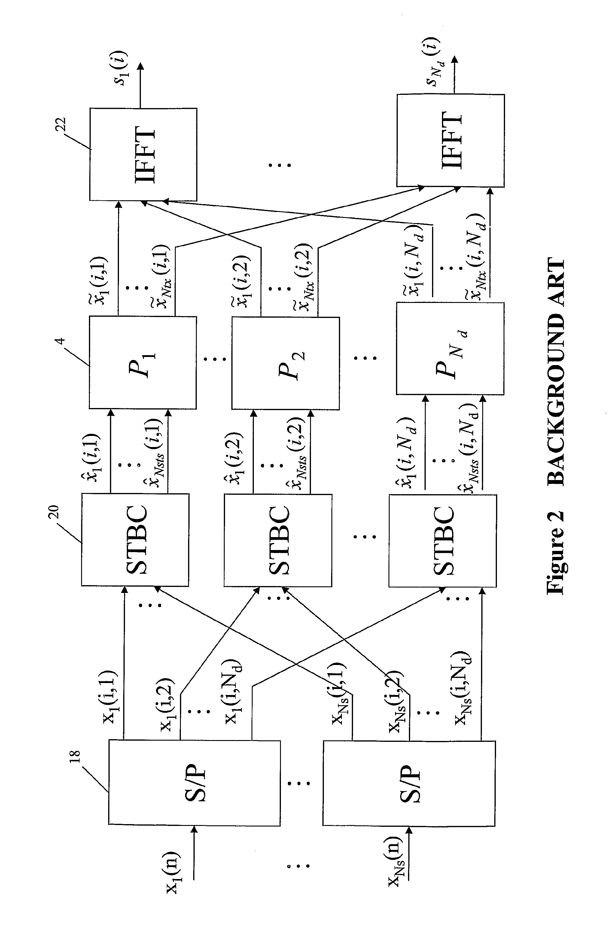
[0064]First, in FIG. 5(A), for the 4 transmit antennas, with Ns=2 spatial streams, and Nsts=4 space-time coded streams, the T and P matrices can be fixed to be 4×4 identity matrices. Thus, the set Ω consists of 3 elements defined as:

Ω={S0=[1000010000100001],S1=[1000001001000001],S2=[1000001000010100]}.

[0065]One example of the predefined permutation pattern, which permutes through all the elements of Q, is:

S(i)=Smod(i,3).

Any known permutation that permutes through all the elements of Ω over the duration of the frame or plural consecutive frames can be used. Other permutation operations or methods for changing the value of the matrix S over the duration of the single frame (or over the duration of the plural consecutive frames) can be used as long as the receiver portion of the transceiver is made aware of, or learns by itself, the transmitter portion's predefined permutation pattern.

[0066]For the 3 transmit antennas, Ns=2 spatial streams, and Nsts=3 space-time coded streams case show...

case 2

2. MIMO-OFDM System Simulation Results

[0078]The structure of the system used in this simulation is shown in FIG. 6(C) and the antenna hopping pattern can be any of the patterns given in the above examples. The simulation parameters are listed as follow:

Channel ModelTGn channel BNumber of TX4Number of RX2STBCSee FIG. 5(A)DemodulatorLMMSE soft demodulator without SICFEC½, ¾ LDPC codes andconvolutional codesFEC decoderBP soft decoder with 30 iterations for LDPC andsoftViterbi for CCChannel seeds10000Modulation16QAM

From the simulation results shown in FIG. 11, it can be seen that the new scheme achieves more than 1 dB gain for all modulation coding settings (MCS) comparative to the situation without antenna hopping. Similarly, FIGS. 12-14 show the gain achieved by the various embodiments of the present invention when quadraphase-shift modulation is used.

[0079]The present invention includes processing of a signal input to the transmitter portion or received at the receiver portion, and ...


PUM


Abstract

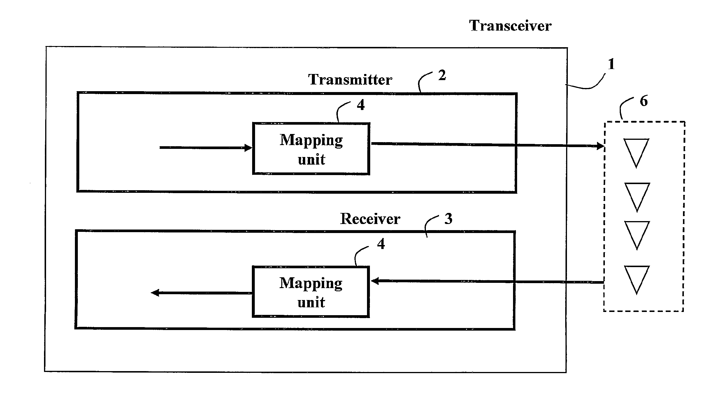
A method, MIMO communication device and electronic storage medium for mapping symbols during a duration of each plural consecutive frames of each of a plurality of first data streams (10, 12, 14, 16, 18, 20, 22, 24, 26) to frames of a plurality of second data streams (spaced-time coded streams or antenna streams); and varying the mapping during the duration of each of the plural consecutive frames of each of the plurality of first data streams (10, 12, 14, 16, 18, 20, 22, 24, 26).

Description

BACKGROUND OF THE INVENTION[0001]1. Field of the Invention[0002]This application relates to mapping signals by a multiple input multiple output communication apparatus. More specifically, this application relates to an apparatus that maps and a mapping method based on time varying mapping.[0003]2. Description of the Related Art[0004]Multiple antenna technique has been adopted by many of the emerging communication standards, such as 3G cellular systems, the 802.11n system and 802.16 WiMax systems. See, for example, D. Gesbert et al., “From theory to practice: an overview of MIMO space-time coded wireless systems,” IEEE Journal on Selected Areas in Communications, vol. 21, pp. 281-301, 2003, the entire contents of which are incorporated herein by reference. Theoretic analysis of communication systems has shown that deploying multiple antennas at both the transmitter side and the receiver side can provide multiple parallel channels to achieve the communication of signals. These multipl...

Claims


Application Information

Patent Timeline
IPC IPC(8): H04L27/00H04B1/38
CPCH04B7/0413H04L27/2626H04L1/0625
Inventor MEHTA, NEELESH B.WANG, DONGZHANG, HONGYUANMOLISCH, ANDREAS F.ZHANG, JINYUN
Owner MITSUBISHI ELECTRIC RES LAB INC
Learn More