Nuclear fuel element and assembly

a fuel element and nuclear technology, applied in nuclear elements, nuclear engineering, greenhouse gas reduction, etc., can solve the problems of fuel assembly damage due to debris, chip and metal particles still remain hidden in the system, debris to gyrate, etc., and achieve the effect of reducing the potential for core plate distortion

Inactive Publication Date: 2010-09-09
WESTINGHOUSE ELECTRIC CORP
View PDF13 Cites 3 Cited by
  • Summary
  • Abstract
  • Description
  • Claims
  • Application Information

AI Technical Summary

Benefits of technology

[0011]Preferably, a transition between the first wall section and the second wall section forms an annular ledge on the interior of the tubular cladding with a larger interior diameter in the second wall section above the transition than exists in the first wall section below the transition. In one of the embodiments, the annular ledge supports the nuclear fuel above the annular ledge for at least a portion of the second preselected distance. Preferably, at least a portion of the first preselected distance forms a gas collection plenum, which distances the active fuel from the lower core plate and reduces the potential for core plate distortion due to gamma heating. Preferably, the first preselected distance is approximately 5.0 inches (12.70 cm).

Problems solved by technology

Although elaborate procedures are carried out to help assure debris removal, experience shows that in spite of the safeguards used to effect such removal, some chips and metal particles still remain hidden in the system.
In particular, fuel assembly damage due to debris trapped at the lower most grid has been noted in several reactors in recent years.
The damage consists of fuel rod tube perforations caused by fretting of the debris in contact with the exterior of the cladding tubes which sealably enclose the fissile material.
Debris also becomes entangled in the bottom nozzle top plate holes and the flowing coolant causes the debris to gyrate, which tends to cut through the cladding of the fuel rods.

Method used


Image

  • Nuclear fuel element and assembly
  • Nuclear fuel element and assembly
  • Nuclear fuel element and assembly

Examples


Embodiment Construction

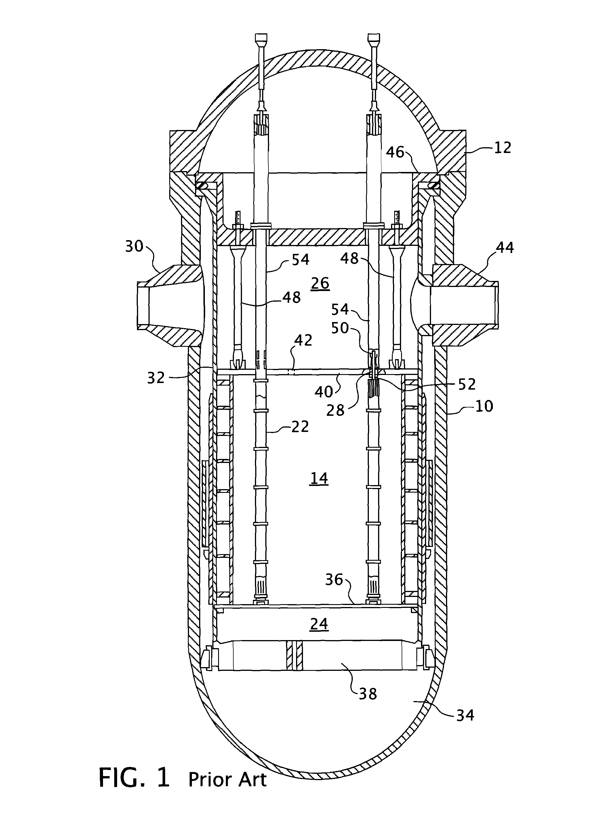
[0020]An exemplary reactor design is shown in FIG. 1. In addition to the core 14 comprised of a plurality of parallel, vertical, co-extending fuel assemblies 22, for the purpose of this description, the other vessel internal structures can be divided into the lower internals 24 and the upper internals 26. In conventional designs the lower internals 24 function to support, align and guide core components and instrumentation as well as direct flow within the vessel. The upper internals 26 restrain or provide a secondary restraint for the fuel assemblies 22 (only two of which are shown for simplicity in this figure), and support and guide instrumentation and components, such as control rods 28. In the exemplary reactor shown in FIG. 1, coolant enters the reactor vessel 10 through one or more inlet nozzles 30, flows down through an annulus between the reactor vessel 10 and the core barrel 32, is turned 180° in a lower plenum 34, passes upward through a lower support plate 38 and a lower...


PUM


Abstract

A nuclear fuel element having a thick walled lower section that transitions to a thinner walled upper section with the transition forming an annular interior ledge that supports the fuel pellets spaced above a bottom end plug. The space between the fuel pellets and the bottom end plug forms a gas collection plenum that assures the necessary void volume exists to maintain margin to rod internal pressure limits.

Description

CROSS REFERENCE TO RELATED APPLICATION[0001]This application claims priority to provisional Application Ser. No. 61 / 158,020, filed Mar. 6, 2009, entitled FUEL TUBE THICK WALL EXTENSION.BACKGROUND OF THE INVENTION[0002]1. Field of the Invention[0003]This present invention relates generally to nuclear reactor fuel assemblies, and more particularly, is concerned with an improved nuclear reactor fuel element.[0004]2. Description of the Related Art[0005]During manufacture, subsequent installation and repair of components of a nuclear coolant circulation system, diligent effort is made to help assure the removal of all debris from the reactor vessel and its associated systems, which circulate coolant throughout the primary reactor coolant loop under various operating conditions. Although elaborate procedures are carried out to help assure debris removal, experience shows that in spite of the safeguards used to effect such removal, some chips and metal particles still remain hidden in the ...

Claims


Application Information

Patent Timeline
Patent Type & Authority Applications(United States)
IPC IPC(8): G21C3/06
CPCG21C3/06Y02E30/40G21C3/16Y02E30/30
Inventor PENDLEY, II, HOWARD A.O'CAIN, MAX B.LEE, YU C.
Owner WESTINGHOUSE ELECTRIC CORP
Why Eureka
Try Eureka