Electronic Parallel Lift And Return To Carry Or Float On A Backhoe Loader

a backhoe loader and electric parallel technology, applied in the direction of vehicle position/course/altitude control, process and machine control, instruments, etc., can solve the problems of increasing operator fatigue and reducing overall work efficiency

Active Publication Date: 2010-09-09
DEERE & CO
View PDF3 Cites 16 Cited by
  • Summary
  • Abstract
  • Description
  • Claims
  • Application Information

AI Technical Summary

Benefits of technology

[0011]The invention provides for other functions for controlling the loader tool such as, for example, return to carry, ret...

Problems solved by technology

Work operation with a loader bucket entails similar problems to those encountered in work operations with the backhoe bucket.
The continual adjustment of the loader tool orientation, combined wit...

Method used


Image

  • Electronic Parallel Lift And Return To Carry Or Float On A Backhoe Loader
  • Electronic Parallel Lift And Return To Carry Or Float On A Backhoe Loader
  • Electronic Parallel Lift And Return To Carry Or Float On A Backhoe Loader

Examples


Embodiment Construction

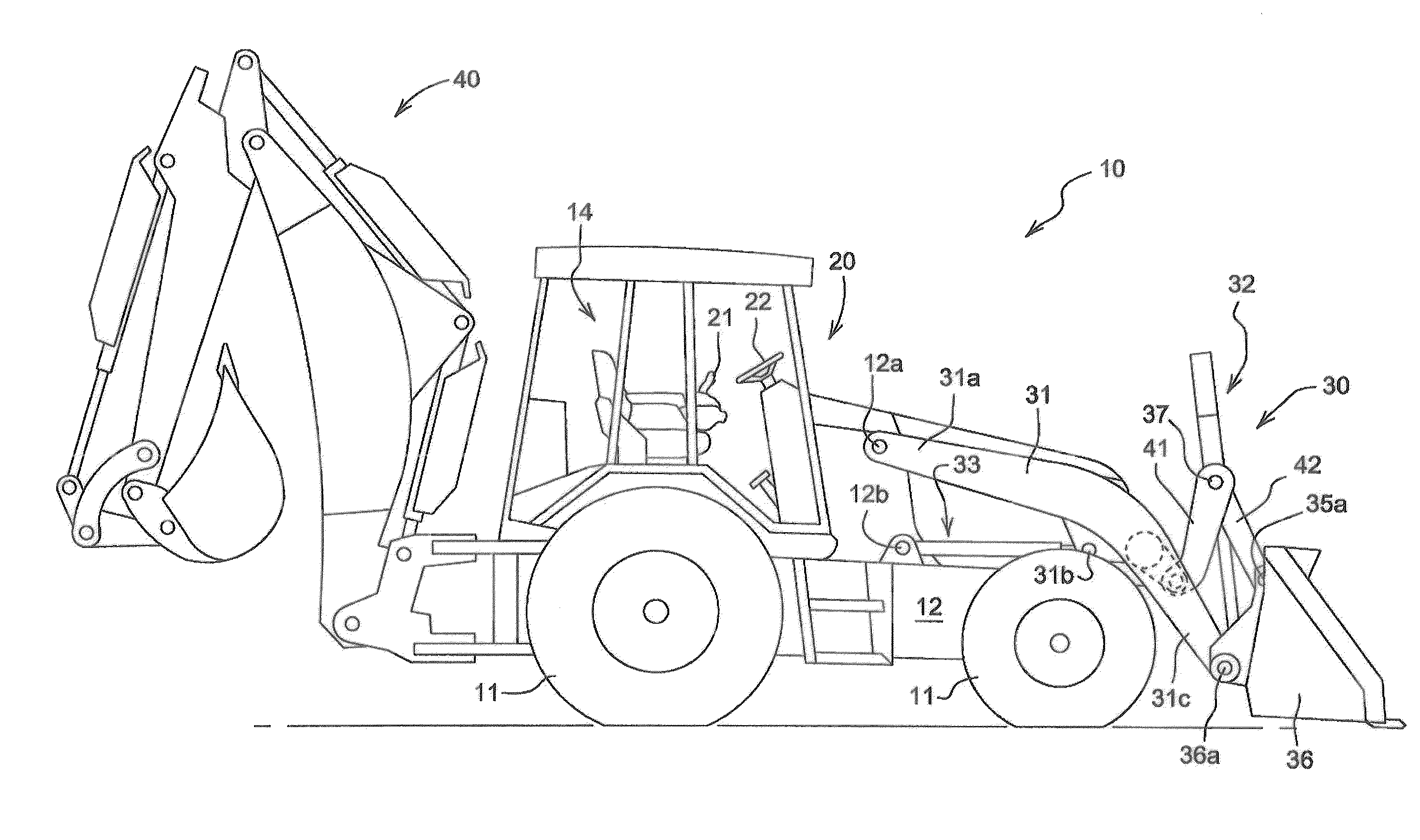
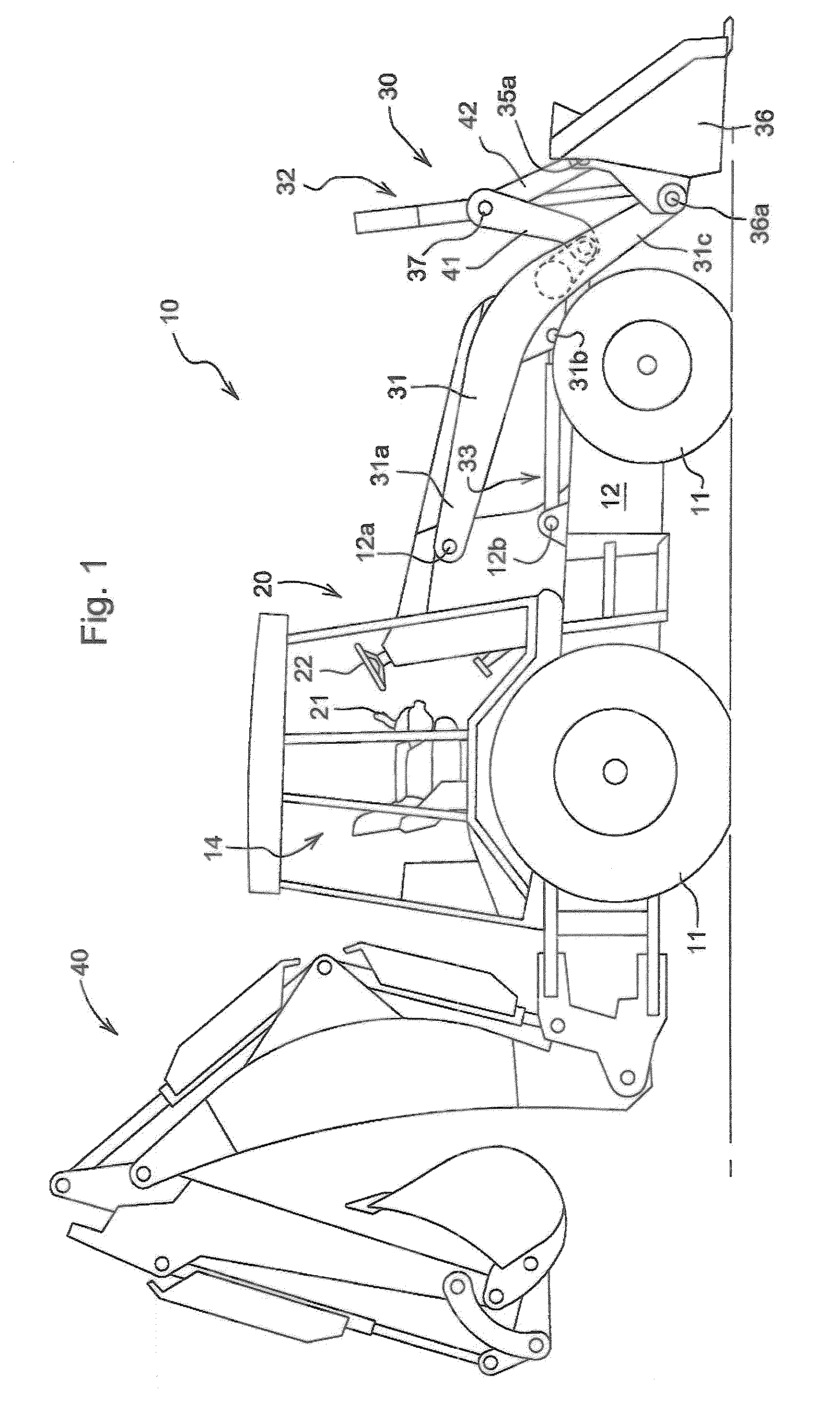
[0028]FIG. 1 illustrates an exemplary work vehicle, i.e., a backhoe loader 10 in which the invention may be utilized. The backhoe loader 10 has a frame 12, to which are attached ground engaging wheels 11 for supporting and propelling the vehicle 10. Attached to the front of the vehicle is a loader assembly 30, and attached to the rear of the vehicle 10 is a backhoe assembly 40. Both the loader assembly 30 and backhoe assembly 40 perform a variety of material handling functions. An operator controls the functions of the vehicle 10 from an operator's station 20.

[0029]This particular loader assembly 30 comprises a loader boom 31, a linkage 40 and a tool such as, for example, a loader bucket 36. The loader boom 31 has a first end 31a pivotally attached to the frame 12 at a horizontal loader boom pivot 12a, and a second end 31c to which the loader bucket 36 pivotally attaches at loader bucket pivot 36a.

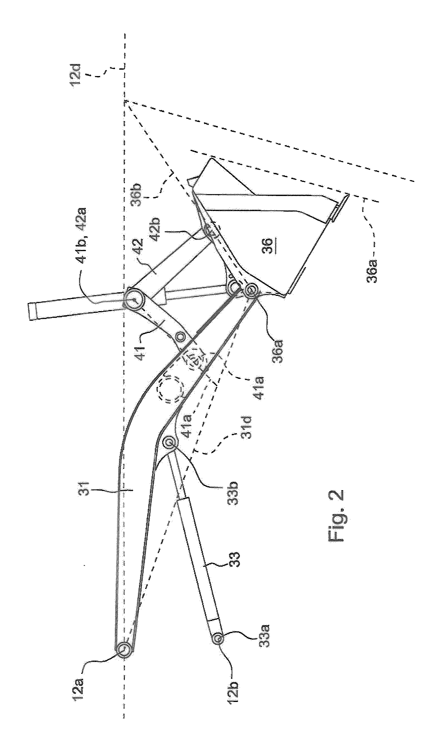
[0030]The linkage 40, illustrated in FIG. 2, includes a boom link 41 and a bucket lin...


PUM


Abstract

A backhoe loader 10 with a controller 100 that uses angular signals from at least one sensor to calculate a loader tool angle with respect to the vehicle frame 12 or with respect to the earth and to maintain the loader tool angle via controller generated commands to a tool actuator 61 as a function of the angular signals and commands to a boom actuator 50. The controller 100 enables proportional control of the tool angle via a command input device such as an electronic joystick 21. If the electronic joystick 21 is moved to an appropriate detent position, the controller executes a return to carry function. If the boom 31 is at or below the return to carry angle at the time the joystick 21 is moved to the detent position, the controller 100 executes a float function allowing the bucket 36 and the boom 31 to rest on the ground and follow the contours of the earth as the vehicle moves over the earth.

Description

FIELD OF THE INVENTION[0001]The invention relates to a system for sensing and automatically controlling the orientation of a work toolBACKGROUND OF THE INVENTION[0002]A variety of work machines can be equipped with tools for performing a work function. Examples of such machines include a wide variety of loaders, excavators, telehandlers, and aerial lifts. A work vehicle such as backhoe loader may be equipped with a backhoe tool, such as a backhoe bucket or other structure, for excavating and material handling functions as well as a loader tool such as a loader bucket.[0003]In the backhoe portion of the backhoe loader, a swing frame pivotally attaches to the vehicle frame at a rear portion of the vehicle, a backhoe boom pivotally attaches to the swing frame, a dipperstick pivotally attaches to the backhoe boom, and the backhoe tool pivotally attaches to the dipperstick about a backhoe tool pivot. A vehicle operator controls the orientation of the backhoe bucket relative to the dipper...

Claims


Application Information

Patent Timeline
IPC IPC(8): E02F3/34E02F3/04
CPCE02F3/434E02F3/432
Inventor TRIFUNOVIC, BORIS
Owner DEERE & CO
Why Eureka
Try Eureka