Fan assembly

a technology of fan assembly and fan body, which is applied in the direction of positive displacement liquid engine, piston pump, liquid fuel engine, etc., can solve the problems of degrading the efficiency of the fan assembly, and achieve the effect of reducing noise and frictional losses

Inactive Publication Date: 2010-09-09
DYSON TECH LTD
View PDF85 Cites 135 Cited by
  • Summary
  • Abstract
  • Description
  • Claims
  • Application Information

AI Technical Summary

Benefits of technology

[0010]The flexible sealing member inhibits the return of air to the air inlet along a path extending between the outer casing and the impeller housing, forcing the pressurized air flow generated by the impeller to be output through the impeller housing and into the nozzle. With this fan assembly a substantially constant pressure difference can be maintained between the motor and the impeller in the base, including the air outlet of the impeller housing, and the air inlet and impeller housing. Without the flexible sealing member the efficiency of the fan assembly would be degraded due to fluctuating losses within the base. Advantageously, the flexible sealing member absorbs some vibration and noise from the motor that would otherwise be transmitted and amplified through the fan assembly by a rigid sealing member.
[0022]Preferably, the mouth of the nozzle extends about the opening, and is preferably annular. Preferably the nozzle extends about the opening by a distance in the range from 50 to 250 cm. The nozzle preferably comprises at least one wall defining the interior passage and the mouth, and wherein said at least one wall comprises opposing surfaces defining the mouth. Preferably, the mouth has an outlet, and the spacing between the opposing surfaces at the outlet of the mouth is in the range from 0.5 mm to 5 mm, more preferably in the range from 0.5 mm to 1.5 mm. The nozzle may preferably comprise an inner casing section and an outer casing section which define the mouth of the nozzle. Each section is preferably formed from a respective annular member, but each section may be provided by a plurality of members connected together or otherwise assembled to form that section. The outer casing section is preferably shaped so as to partially overlap the inner casing section. This can enable an outlet of the mouth to be defined between overlapping portions of the external surface of the inner casing section and the internal surface of the outer casing section of the nozzle. The nozzle may comprise a plurality of spacers for urging apart the overlapping portions of the inner casing section and the outer casing section of the nozzle. This can assist in maintaining a substantially uniform outlet width about the opening. The spacers are preferably evenly spaced along the outlet.

Problems solved by technology

Without the flexible sealing member the efficiency of the fan assembly would be degraded due to fluctuating losses within the base.

Method used


Image

  • Fan assembly
  • Fan assembly
  • Fan assembly

Examples


Embodiment Construction

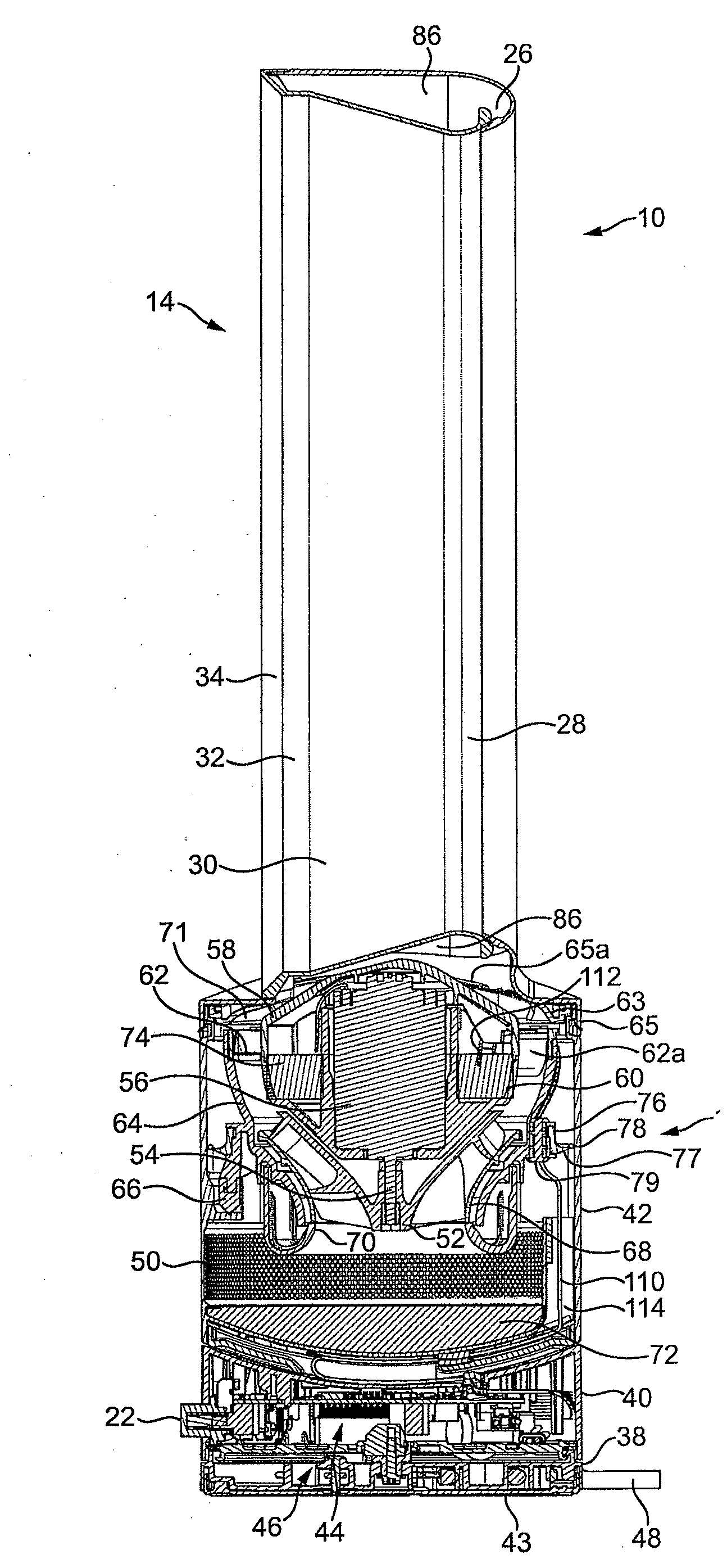
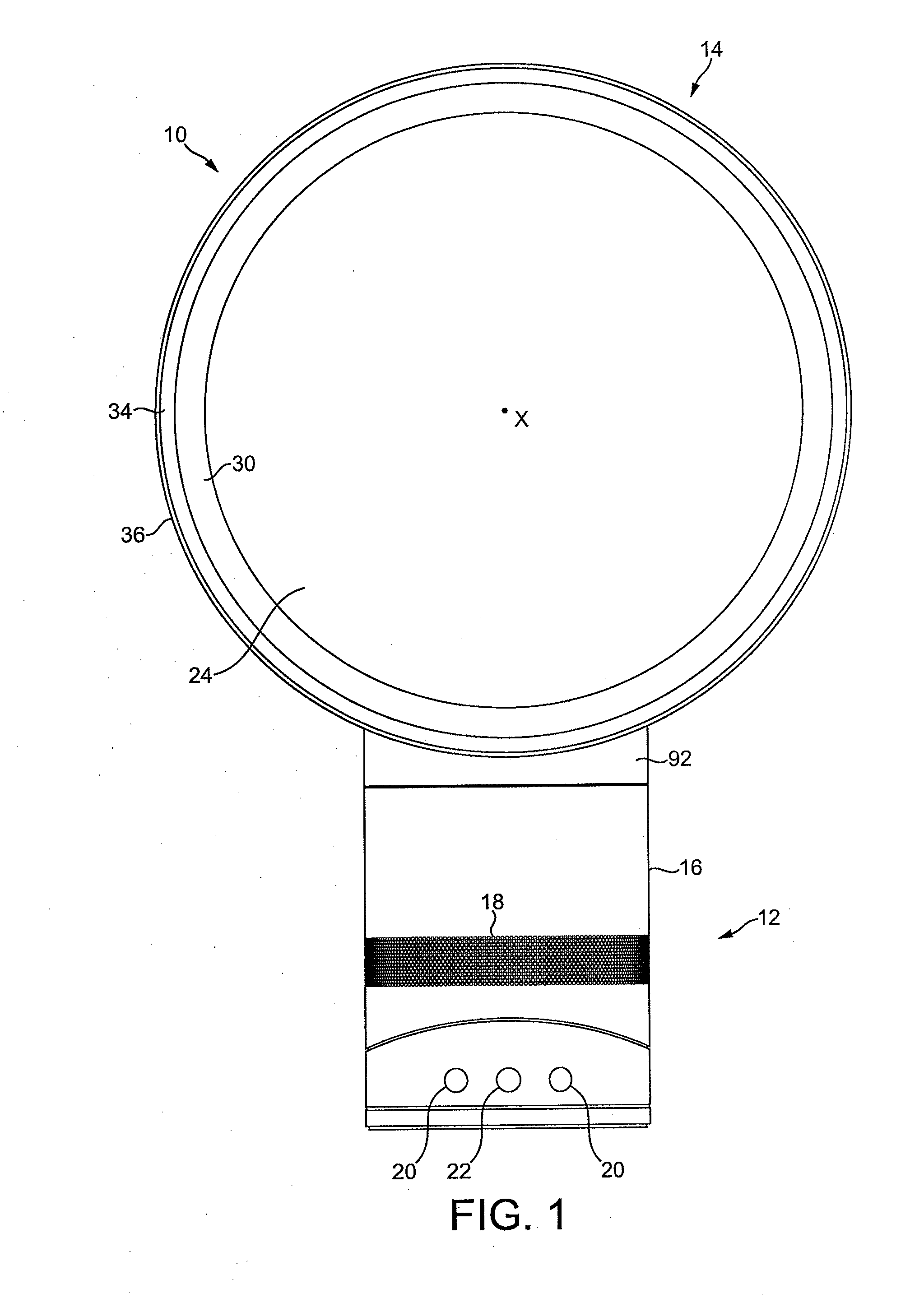
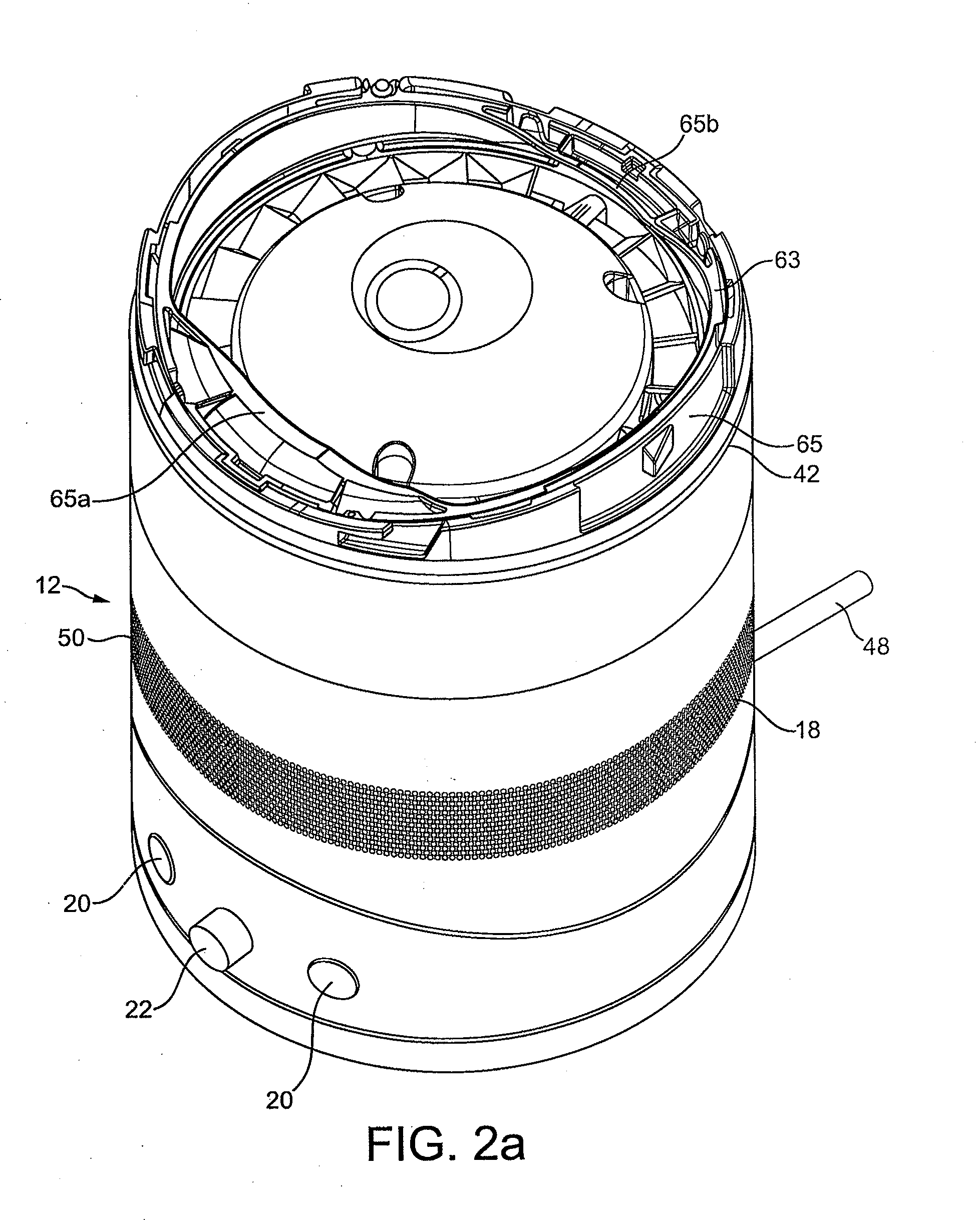
[0045]FIG. 1 is a front view of a fan assembly 10. The fan assembly 10 is preferably in the form of a bladeless fan assembly comprising a base 12 and a nozzle 14 mounted on and supported by the base 12. With reference to FIG. 2(a), the base 12 comprises a substantially cylindrical outer casing 16 having a plurality of air inlets 18 in the form of apertures located in the outer casing 16 and through which a primary air flow is drawn into the base 12 from the external environment. The base 12 further comprises a plurality of user-operable buttons 20 and a user-operable dial 22 for controlling the operation of the fan assembly 10. In this example the base 12 has a height in the range from 200 to 300 mm, and the outer casing 16 has an external diameter in the range from 100 to 200 mm.

[0046]With reference also to FIG. 2(b), the nozzle 14 has an annular shape and defines a central opening 24. The nozzle 14 has a height in the range from 200 to 400 mm. The nozzle 14 comprises a mouth 26 lo...


PUM


Abstract

A fan assembly for creating an air current includes a nozzle mounted on a base. The base comprises an outer casing, an impeller housing located within the outer casing, the impeller housing having an air inlet and an air outlet, an impeller located within the impeller housing and a motor for driving the impeller to create an air flow through the impeller housing. The nozzle includes an interior passage for receiving the air flow from the air outlet of the impeller housing and a mouth through which the air flow is emitted from the fan assembly. A flexible sealing member is located between the outer casing and the impeller housing.

Description

REFERENCE TO RELATED APPLICATIONS[0001]This application claims the priority of United Kingdom Application No. 0903695.5 filed 4 Mar. 2009, the entire contents of which are incorporated herein by reference.FIELD OF THE INVENTION[0002]The present invention relates to a fan assembly. Particularly, but not exclusively, the present invention relates to a domestic fan, such as a desk fan, for creating air circulation and air current in a room, in an office or other domestic environment.BACKGROUND OF THE INVENTION[0003]A conventional domestic fan typically includes a set of blades or vanes mounted for rotation about an axis, and drive apparatus for rotating the set of blades to generate an air flow. The movement and circulation of the air flow creates a ‘wind chill’ or breeze and, as a result, the user experiences a cooling effect as heat is dissipated through convection and evaporation.[0004]Such fans are available in a variety of sizes and shapes. For example, a ceiling fan can be at lea...

Claims


Application Information

Patent Timeline
Patent Type & Authority Applications(United States)
IPC IPC(8): F01D25/00
CPCF04D25/08F04F5/16F04D29/083F04D29/4226F04D29/441F04D29/44F04D29/08
Inventor CRAWFORD, TOM VALLANCE HAMILTONOSBORN, CHRISTOPHER SIMONSIMMONDS, KEVIN JOHNNICOLAS, FREDERICCODLING, JONATHAN RICHARD
Owner DYSON TECH LTD
Why Eureka
Try Eureka