Film deposition apparatus, film deposition method, and computer readable storage medium
a film deposition apparatus and film deposition technology, applied in liquid surface applicators, metal material coating processes, coatings, etc., can solve the problems of difficult control of reaction gas flow patterns and degrade thickness uniformity, and achieve the effect of improving the uniformity of films
- Summary
- Abstract
- Description
- Claims
- Application Information
AI Technical Summary
Benefits of technology
Problems solved by technology
Method used
Image

Examples
first embodiment
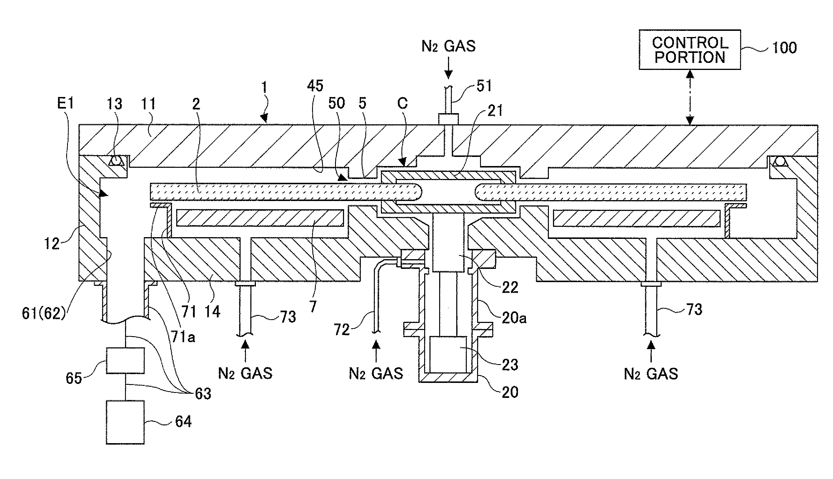
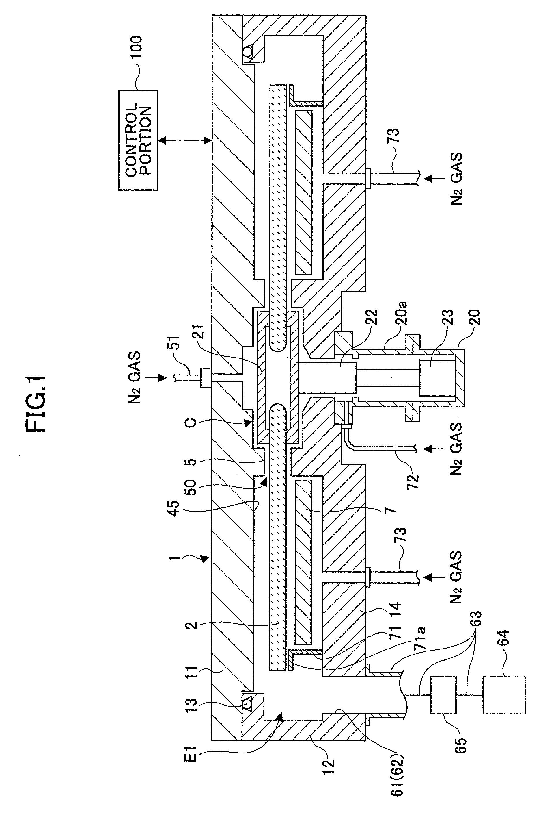
[0069]As shown in FIGS. 1 through 3, a film deposition apparatus according to an embodiment of the present invention is provided with a substantially flattened vacuum chamber 1 having a cylinder top view shape, and a susceptor 2 that is arranged inside the vacuum chamber 1 and has a rotation center at a center of the vacuum chamber 1. The vacuum chamber 1 is provided with a chamber body 12 that has a substantially cup-shape to accommodate the susceptor 2, and a ceiling plate 11 configured to hermetically close a top opening of the chamber body 12. The ceiling plate 11 is hermetically coupled with the chamber body 12 via a sealing member 13 such as an O-ring that has a ring shape and is placed on a circumferential top surface of the chamber body 12. The ceiling plate 11 can be brought upward from and downward on the chamber body 12 by a driving mechanism (not shown).
[0070]The susceptor 2 is made of a carbon plate having a thickness of about 20 mm in this embodiment, and has a circula...
second embodiment
[0128]While the film deposition apparatus according to the first embodiment is provided with the elevation mechanism 18 that brings upward / downward and rotates the wafer W, a film deposition apparatus according to a second embodiment is provided with an elevation mechanism and a rotation mechanism that are separated from each other. Specifically, a through-hole 210 is formed above the lift pins 16 and in the ceiling plate 11, and an elevation shaft 211 is provided in order to extend from above the ceiling plate 11 into the vacuum chamber 1 through the through-hole 210, as shown in a subsection (a) of FIG. 15. In addition, a rotation mechanism 212 that rotates the elevation shaft 211 around a vertical axis thereof is arranged on the ceiling plate 11. The rotation mechanism 212 can bring the elevation shaft 211 upward / downward. Moreover, an elevation plate 213 is connected to a bottom end of the elevation shaft 211, and holding mechanisms 214, 214 having an inner indented portion for ...
third embodiment
[0130]While the susceptor 2 is rotated in relation to the gas nozzles 31, 32, 41, 42 in the above embodiments, the gas nozzles 31, 32, 41, 42 may be rotated in relation to the stationary susceptor 2. As a third embodiment, a configuration that enables such relative rotation is explained with reference to FIGS. 16 through 20.
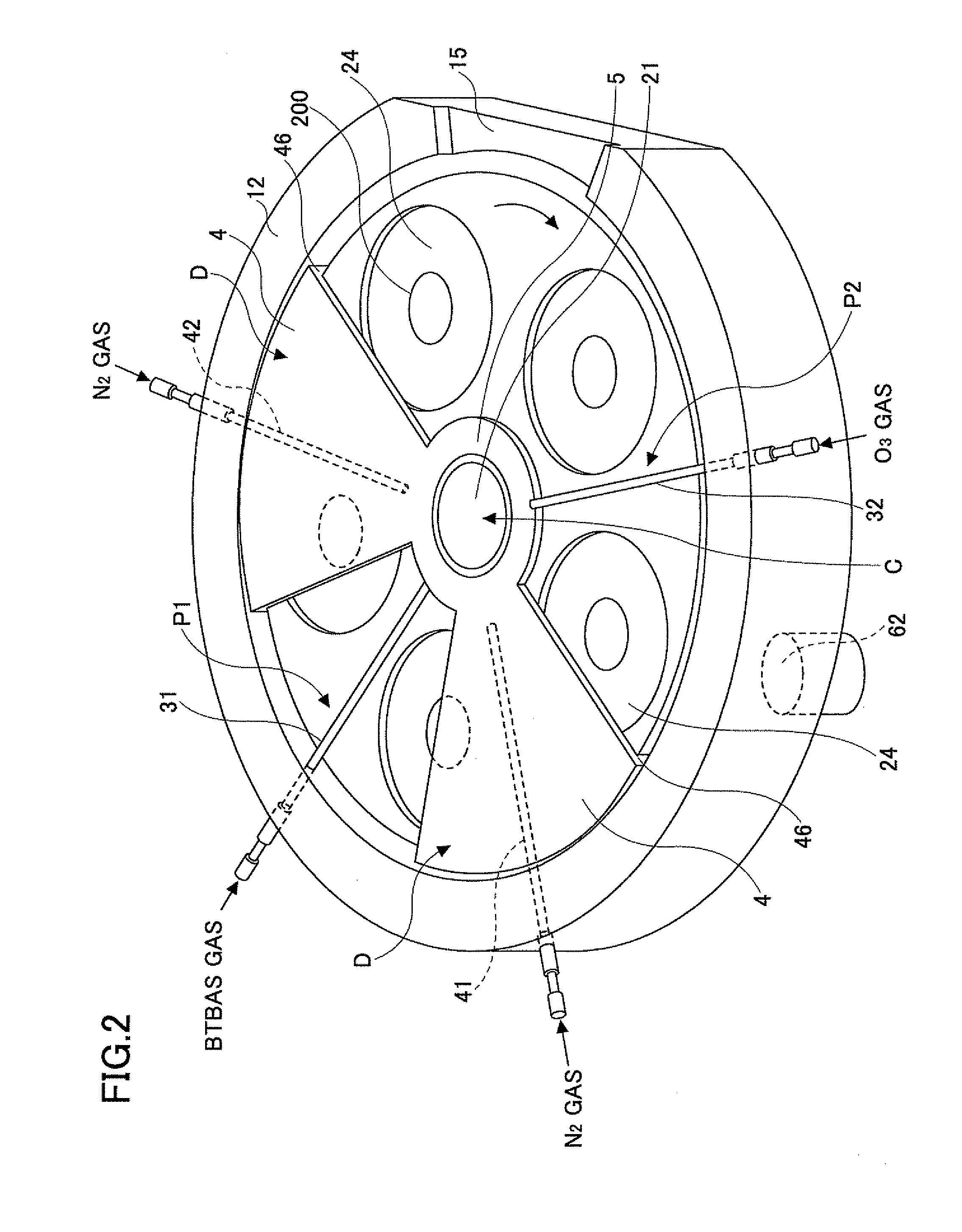
[0131]A susceptor 300 is provided in the vacuum chamber 1, in the place of the susceptor 2 explained in the above embodiments. A rotational shaft 22 is connected to a center of a lower surface of the susceptor 300 in order to rotate the susceptor 300 when the wafers W are placed on and removed from the susceptor 300. Five wafer receiving portions 24, each of which has the elevation plate 200, are formed on the susceptor 300 in this embodiment.
[0132]As shown in FIGS. 16 through 18, the gas nozzles 31, 32, 41, 42 are attached to a planar core portion 301 that has a disk shape and are provided above a center portion of the susceptor 300. Base portions of the gas noz...
PUM
| Property | Measurement | Unit |
|---|---|---|
| diameter | aaaaa | aaaaa |
| thickness | aaaaa | aaaaa |
| diameter | aaaaa | aaaaa |
Abstract
Description
Claims
Application Information
 - R&D
- Intellectual Property
- Life Sciences
- Materials
- Tech Scout
- Unparalleled Data Quality
- Higher Quality Content
- 60% Fewer Hallucinations
Browse by: Latest US Patents, China's latest patents, Technical Efficacy Thesaurus, Application Domain, Technology Topic, Popular Technical Reports.
© 2025 PatSnap. All rights reserved.Legal|Privacy policy|Modern Slavery Act Transparency Statement|Sitemap|About US| Contact US: help@patsnap.com