Method for fabricating wick microstructures in heat pipes

a technology of wick and microstructure, which is applied in the direction of heat exchangers, indirect heat exchangers, lighting and heating apparatus, etc., can solve the problems of increasing the difficulty of thermal management, shortened the use life of electronic components, and decreased clock speed and operation efficiency, so as to achieve the effect of easy understanding

Inactive Publication Date: 2010-09-16
IND TECH RES INST
View PDF13 Cites 6 Cited by
  • Summary
  • Abstract
  • Description
  • Claims
  • Application Information

AI Technical Summary

Benefits of technology

[0014]To make the examiner easier to understand the objectives, structure, innovative features, and function of the inven...

Problems solved by technology

Thus, the density of giving out heat in electronic components is higher and higher such that thermal management is more and more difficult.
If thermal management of an electronic system is not good, increased junction temperature will cause decreased clock speed and operation efficiency, even a shortened usage life of the electronic component.
Therefore, thermal management of electronic components is becoming a key issue concerned by electronic product manufacturers.
In addition, when heat given out by electronic components such as CPU of a personal computer is increased, a difficult problem of heat being not uniformly given out is accompanied simultaneously thus hot spots will be formed on surfaces of the electronic components.
(1) sintered wick structures: (a) U.S. Pat. No. 4,274,479 disclosing wick structures in heat pipes by using sintered grooves, wherein the grooves may be made in any desired crossectional configuration. Thus, the wick structures on inner surface of the heat pipe are in the shapes of groove or others and...

Method used


Image

  • Method for fabricating wick microstructures in heat pipes
  • Method for fabricating wick microstructures in heat pipes
  • Method for fabricating wick microstructures in heat pipes

Examples


Embodiment Construction

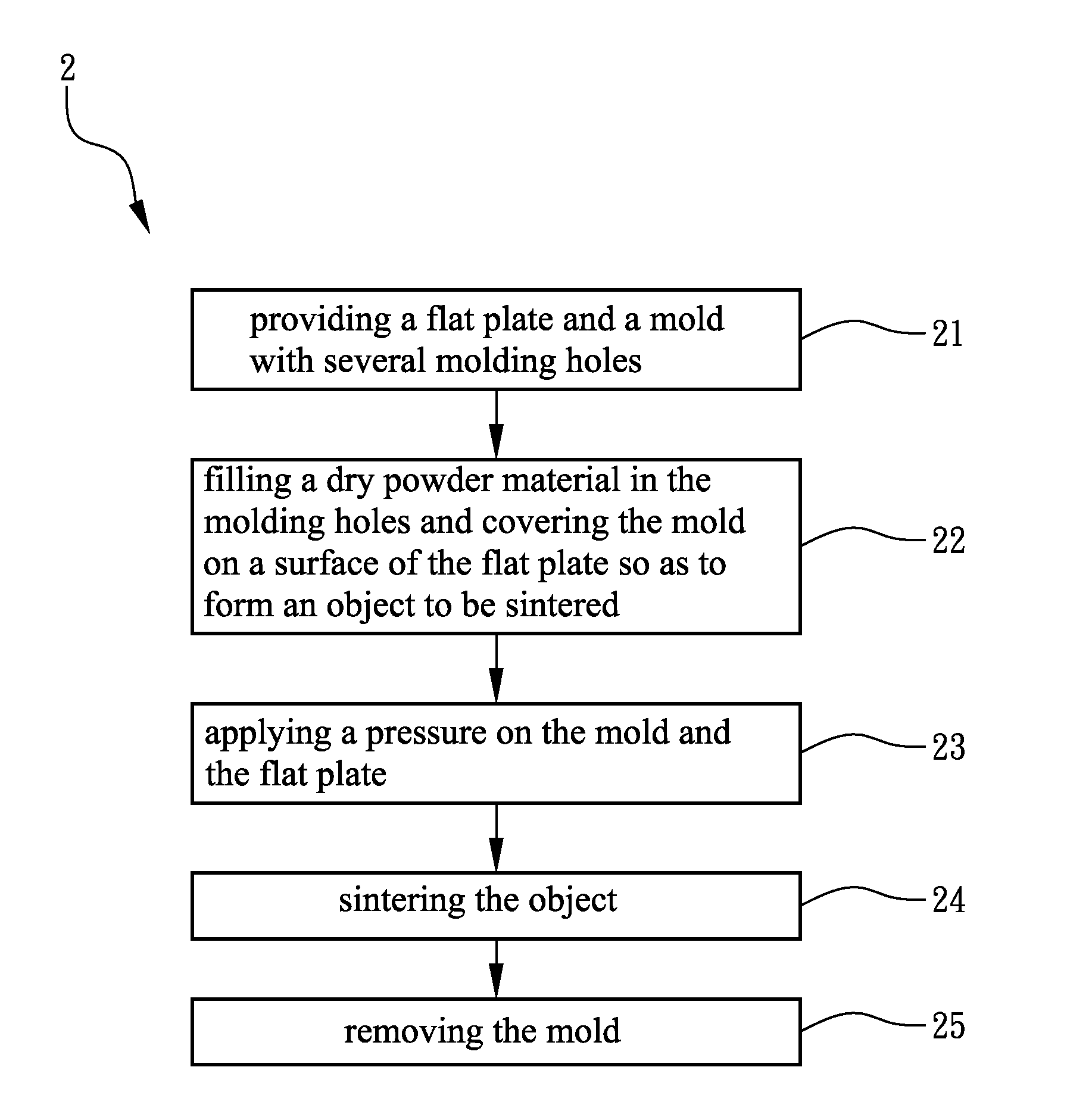
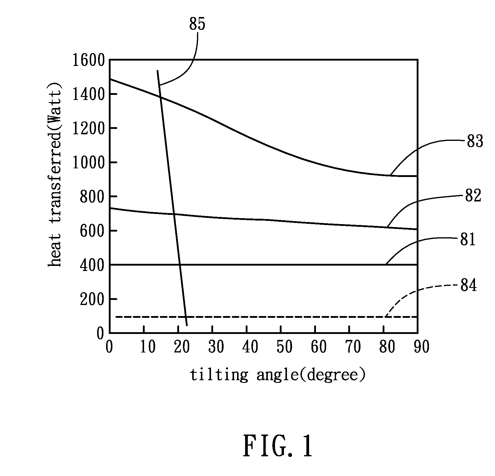
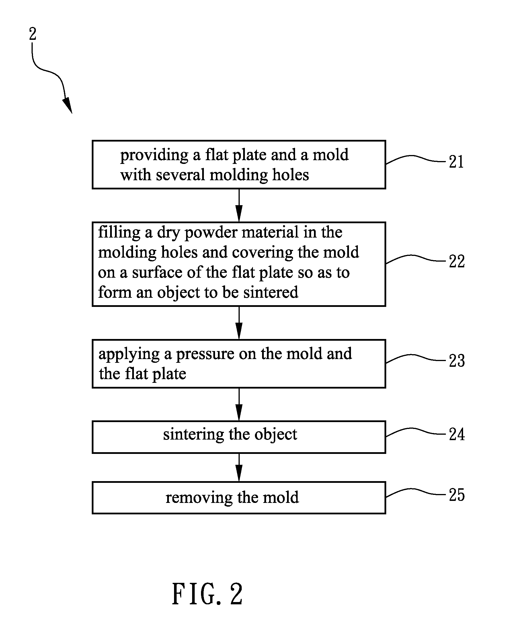
[0026]FIG. 1 is a diagram showing relations of heat transfer capability and tilting angle of various wick structures when depth of the wick structures is 1.0 mm. In FIG. 1, curve 81 represents a grooved wick microstructure sintered with powders having a diameter of 50 μm by the method of the present invention, curve 82 represents a grooved wick microstructure sintered with powders having a diameter of 100 μm by the method of the present invention, and curve 83 represents a grooved wick microstructure sintered with powders having a diameter of 200 μm by the method of the present invention. Curve 84 represents a simply sintered wick structure with no particular shape, which is merely sintered with a layer of powders, and curve 85 represents an ordinary grooved wick structure. It can be found in FIG. 1 that heat transferred by the wick structure of curve 84 when operated with a tilting angle will not be influenced much since this kind of wick structure has smaller apertures such that t...


PUM

PropertyMeasurementUnit
Porosityaaaaaaaaaa
Pressureaaaaaaaaaa
Shapeaaaaaaaaaa

Abstract

The invention provides a method for fabricating wick microstructures in heat pipes, comprising the following steps: providing a flat plate and a mold with several molding holes; filling a dry powder material in the several molding holes and putting the mold to cover the flat plate so as to form an object to be sintered; sintering the object; and removing the mold to form a flat plate with wick microstructures. The wick microstructures are arranged on the flat plate in a form of microgrooves, microcylinders or any combination of them. The flat plate with wick microstructures is further processed to form a heat pipe with a characteristic shape and having two kinds of wick microstructures such that the heat transferred by the heat pipe is increased and the occurrence of dry out of the heat pipe is delayed.

Description

CROSS REFERENCE TO RELATED DOCUMENT[0001]This application is a continuation-in-part of U.S. patent application Ser. No. 11 / 132,220 filed on May 19, 2005 for Method For Fabricating Wick Microstructures in Heat Pipes”.FIELD OF THE INVENTION[0002]The present invention relates to a method for fabricating wick microstructures in heat pipes, more particularly to a method for fabricating wick microstructures in heat pipes, in which the wick microstructures are arranged in any size on any area of inner surface of heat pipes by sintering.BACKGROUND OF THE INVENTION[0003]As time goes by, heat generated in each unit electronic component is increasing. Besides, miniaturizing of electronic packages and integrating more functions into a microsystem are occurring simultaneously. Thus, the density of giving out heat in electronic components is higher and higher such that thermal management is more and more difficult. If thermal management of an electronic system is not good, increased junction temp...

Claims


Application Information

Patent Timeline
IPC IPC(8): B21D53/02
CPCB23P2700/09F28D15/0233Y10T29/49353F28F2255/18F28D15/046
Inventor TSAI, MING-JYESHYU, JIN-CHERNGCHOU, CHENG-TAICHIANG, CHIA-SHENGYEH, LAN-KAICHEN, SHAO-WEN
Owner IND TECH RES INST
Why Eureka
Try Eureka