Retrofit Grain Dryer Moisture Controller

a technology of moisture controller and retrofit grain dryer, which is applied in the direction of drying machines with progressive movements, static/dynamic balance measurement, instruments, etc., can solve the problems of drying a commodity, inability to always maintain the initial moisture of the grain, and excess shrinkage and lightening of the grain, etc., and achieves the effect of simple installation method

Active Publication Date: 2010-09-16
SALISBURY NOBLE M
View PDF16 Cites 19 Cited by
  • Summary
  • Abstract
  • Description
  • Claims
  • Application Information

AI Technical Summary

Benefits of technology

[0009]The present invention is a retrofit unit specially configured for retrofitting an existing grain dryer with a moisture controller system, as well as the method used and the system created thereby. The retrofit unit includes a grain turner for moving grain from a central portion in the grain pathway to a defined outer space for measurement. The retrofit unit also includes a moisture sensor and a temperature sensor positioned beneath the grain turner for sensing moisture and temperature of grain in the defined space. The retrofit unit allows a simple method of installation, and provides controlled and accurate readings in a robust and long lasting system.

Problems solved by technology

In these grain dryers, the removal of too little moisture doesn't adequately preserve the grain, but the removal of too much moisture not only wastes fuel but also can result in excess shrinkage and lightening of the grain.
Additionally, the initial moisture of the grain is not always constant, but rather can change from time to time and in different grain samples.
With these prior art temperature-only based drying systems, a major problem is drying a commodity with a small moisture point removal or small moisture differential being achieved.
The grain will not rise to a high enough column temperature to allow the temperature-based system to control the unload system accurately without producing an over-dried product.
The prior art temperature-based system thus wastes liquid propane, natural gas and / or electricity in the process, and results in a lower-than-desired final product test weight per volume.
While the modern grain dryers and control systems are beneficial, they have significant limitations and problems.
The humidity sensors used are often difficult to keep accurate, with the accuracy problems being exacerbated due to the debris that comes from the commodity or corn.
When inaccurate sensor readings are provided to the controller / processor, the system will ultimately unload the dryer at an inaccurate speed.
The problem will persist if the sensors or sensor fins are not cleaned daily (or more often), which often does not occur in the field.
A more pervasive problem with modern grain dryers and control systems stems from the fact that improvements to the control systems are usually made by the same company selling the grain dryer itself, and the control systems improvements are used to market new grain dryers.
Grain dryer manufacturers have little incentive to produce systems that will last for decades, when they would rather sell new grain dryers with the latest and greatest control system.

Method used


Image

  • Retrofit Grain Dryer Moisture Controller
  • Retrofit Grain Dryer Moisture Controller
  • Retrofit Grain Dryer Moisture Controller

Examples


Embodiment Construction

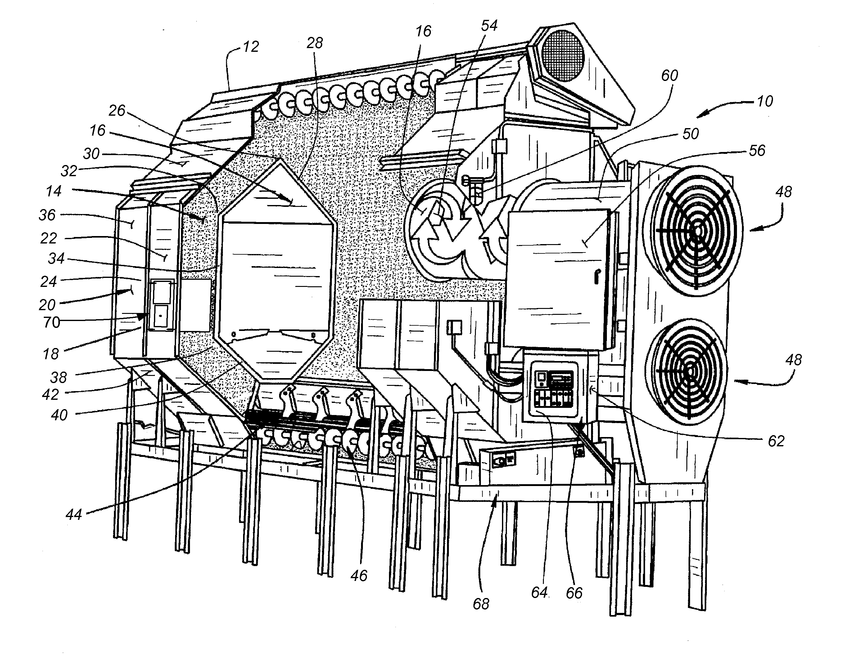
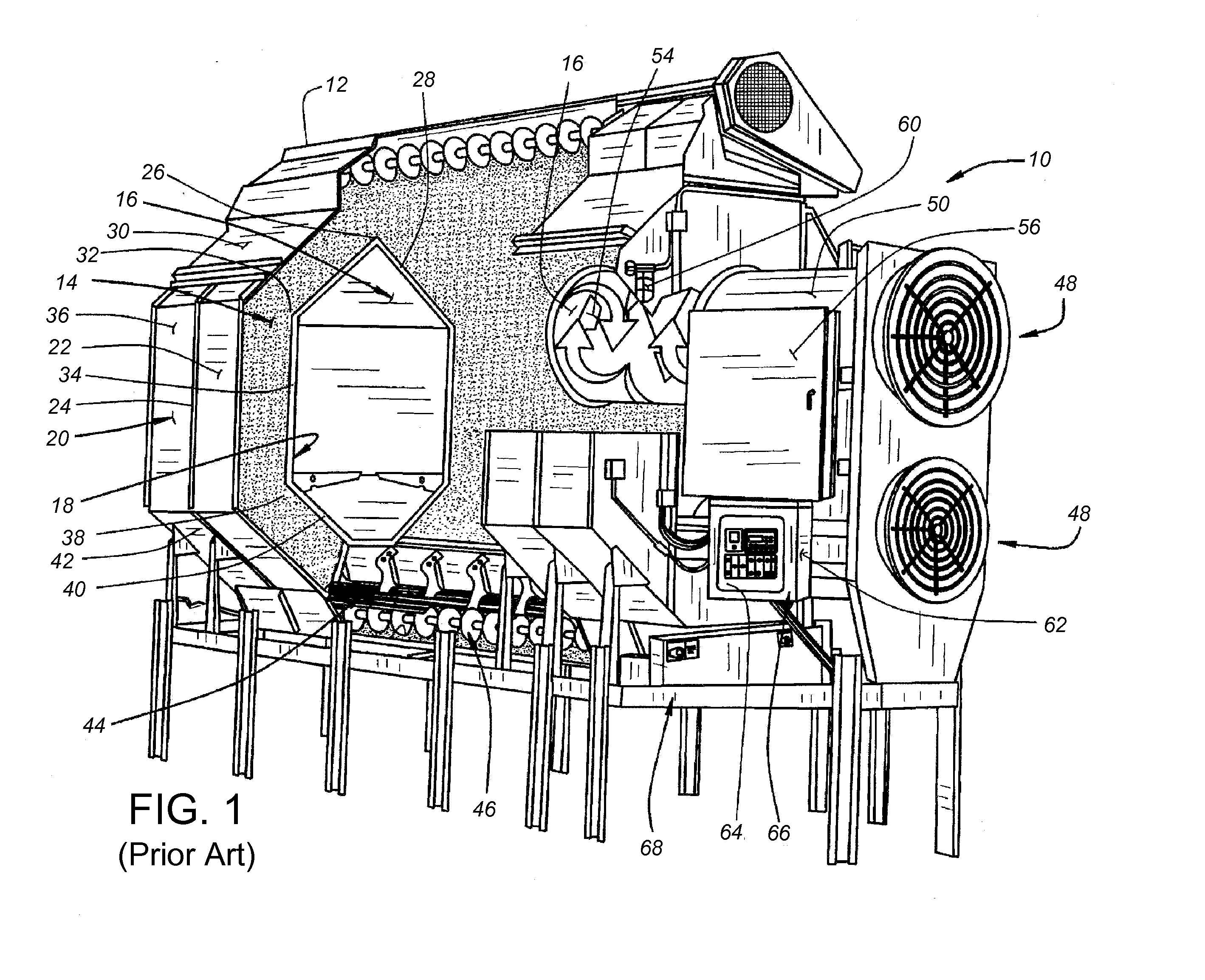
[0018]In the most common types of existing grain dryer 10 exemplified in FIG. 1, moist grain (typically corn) is gravitationally fed from a grain intake 12 down in two pathways 14 around a central dryer chamber or plenum 16. The two grain pathways 14 are defined between inner and outer baskets 18, 20 formed of perforated screen panels 22 secured between vertically extending columns 24. The grain pathways 14 each proceed downwardly and outwardly from a central apex 26 between inner and outer upper inclined panels 28, 30 to an upper shoulder 32. From the upper shoulder 32, each grain pathway 14 proceeds vertically downward between vertical side panels 34, 36 to a lower shoulder 38. From the lower shoulder 38, each grain pathway 14 proceeds downwardly and inwardly between inner and outer lower converging panels 40, 42 through metering rolls 44 to converge at a discharge auger 46. The openings in the perforated screen panels 22 are sized to confine the grain in the grain pathways 14 but...


PUM

PropertyMeasurementUnit
depthaaaaaaaaaa
temperatureaaaaaaaaaa
thickaaaaaaaaaa

Abstract

A retrofit turner and sensor unit includes, on its upper portion, a grain turner for moving grain from a central portion in the grain pathway to a defined outer space for measurement. On its lower portion, the retrofit unit includes a moisture sensor and a temperature sensor provided in a plate configuration in line with the outer wall of the grain dryer for sensing moisture and temperature of grain in the defined space. In the preferred configuration, the plate sensor includes redundancies, and is mounted on a hinged door. The retrofit unit is easily installed into an existing grain dryer with columns and continuous flow capabilities, and electrically connected with a controller/processor and a motor for metering rolls which determine grain speed through the dryer.

Description

CROSS-REFERENCE TO RELATED APPLICATION(S)[0001]This application claims priority from Provisional Application No. 61 / 159,909, filed Mar. 13, 2009, entitled MOISTURE CONTROLLER FOR GRAIN DRYER.BACKGROUND OF THE INVENTION[0002]The present invention relates to control of the level of moisture in grain dryers, and to automated or semi-automated moisture controllers used in grain dryers, such as in continuous flow corn dryers. More particularly, the present invention relates to methods and structures for retrofitting existing grain dryers with a control system to regulate the grain dryer to operate to a desired level of moisture in the dried grain.[0003]Freshly harvested grain frequently requires some degree of drying prior to storage to prevent spoilage, and grain dryers are well known in the agricultural arts. In these grain dryers, the removal of too little moisture doesn't adequately preserve the grain, but the removal of too much moisture not only wastes fuel but also can result in e...

Claims


Application Information

Patent Timeline
Patent Type & Authority Applications(United States)
IPC IPC(8): F26B21/08B21D39/03F26B17/12G05B15/00
CPCF26B17/122F26B25/02Y10T29/49716F26B21/06Y10T29/49826F26B25/22
Inventor SALISBURY, NOBLE M.
Owner SALISBURY NOBLE M
Why Eureka
Try Eureka