
Inflatable heliostatic solar power collector

a solar power collector and heliostatic technology, applied in solar radiation transmission, sustainable buildings, light and heating equipment, etc., can solve the problems of high power cost per unit, and achieve the effects of reducing cost, low cost, and increasing conversion efficiency

Active Publication Date: 2010-09-16
RIC ENTERPRISES
View PDF55 Cites 78 Cited by
  • Summary
  • Abstract
  • Description
  • Claims
  • Application Information

AI Technical Summary

Benefits of technology

[0003]The present invention provides further inventive development of inflatable heliostat devices, with added novelty in multiple areas. More specifically, the present invention provides for low-cost inflatable heliostatic solar power collectors, which are stand-alone units suitable for use in small, medium, or utility scale applications, as opposed to prior art “power tower” concepts best suited for utility scale application. In one preferred embodiment the inflatable heliostatic power collector uses a reflective surface or membrane “sandwiched” between two inflated chambers, and an elongated solar power receiver which receives solar insolation reflected and concentrated by this reflective surface.
[0004]The power receiver may be of photovoltaic and / or solar thermal types, in variant preferred embodiments of the invention. The utilization of modest concentration ratios enables benefits in both reduced cost and increased conversion efficiency, relative to simple prior-art flat plate solar collectors.
[0005]In a preferred embodiment the inflatable structure includes inventive application of simple lightweight and low cost frame members, and heliostatic aiming for azimuth and elevation control using simple and low cost motorized control means. The invention provides great flexibility and value in tailored applications using varying numbers of the low-cost inflatable heliostatic power collectors, of varying scalable size designs, for optimal use in applications ranging from (i) one or a few units for private home installations on a rooftop or back-yard, to (ii) estate / farm / ranch / commercial building installations with a small / medium field of units, to (iii) utility scale installations with medium / large / very large field(s) of units.

Problems solved by technology

Limitations to the widespread deployment of solar power, either solar photovoltaic power or solar thermal power, have largely been a consequence of higher power cost per kilowatt-hour for traditional solar power systems as compared with fossil fuel power systems, driven in large part by the cost to make these solar power systems.

Method used


Image

  • Inflatable heliostatic solar power collector
  • Inflatable heliostatic solar power collector
  • Inflatable heliostatic solar power collector

Examples


Embodiment Construction

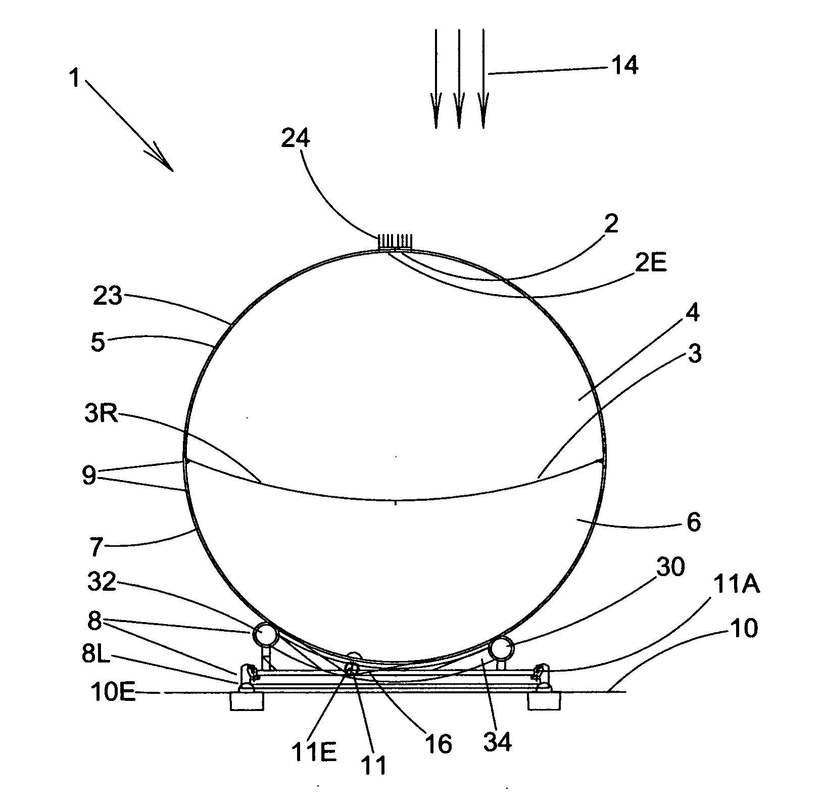
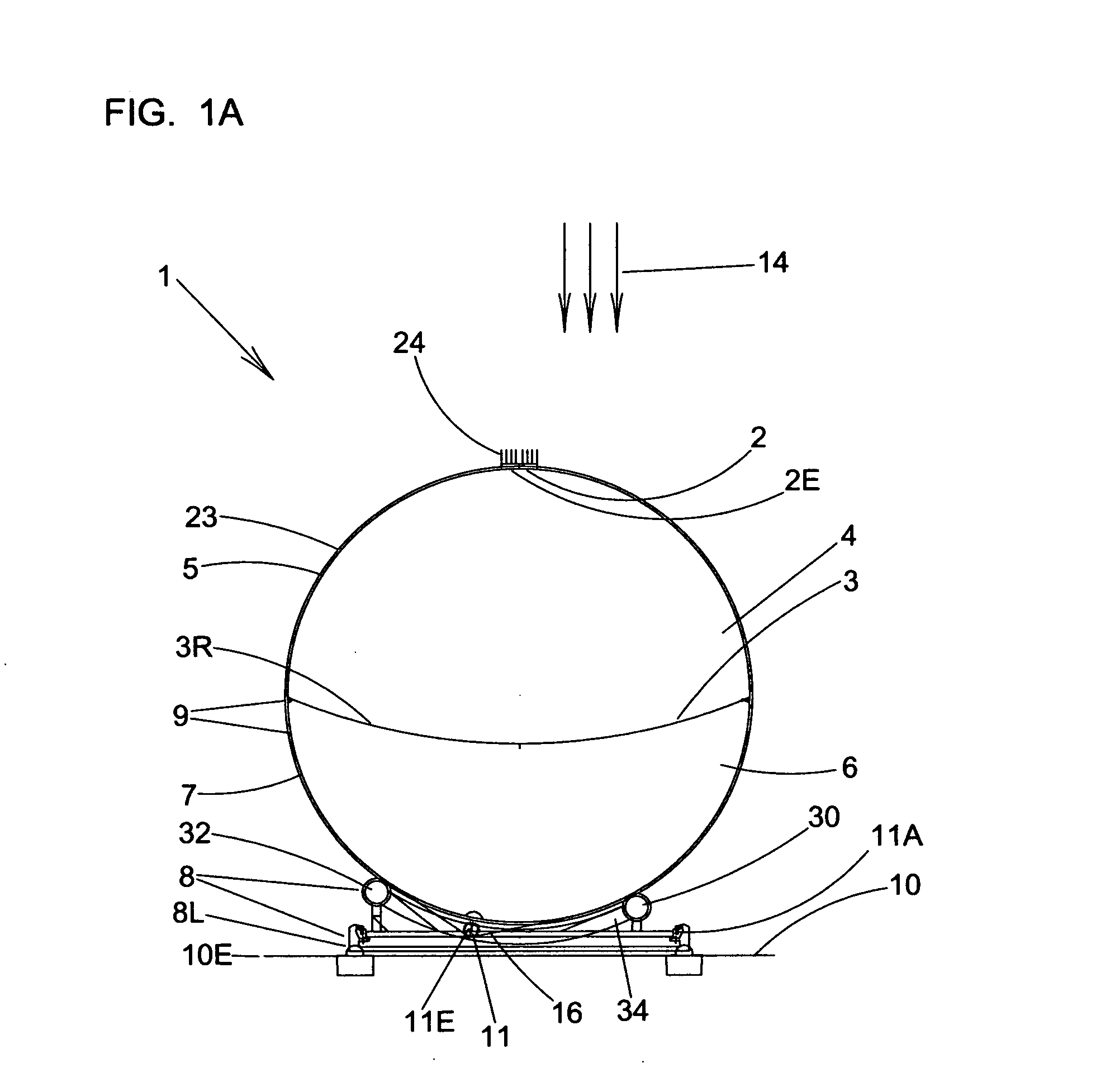
[0036]FIG. 1A shows a left end view of a preferred embodiment of the invention, an inflatable heliostatic solar power collector 1 that applies an ingenius lightweight inflatable structural design to enable concentrating solar powerplants with elongated solar receivers that can be made at unprecedented low cost—for small, medium and large-scale applications for electricity and / or heat generation from clean, renewable and plentiful solar power coming from the Sun.

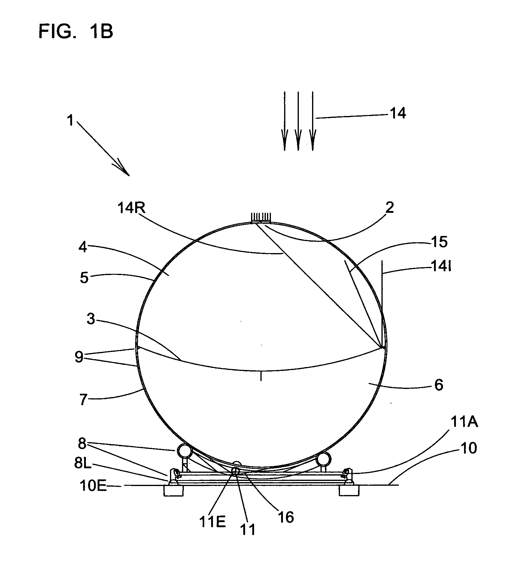
[0037]An inflatable heliostatic solar power collector 1 is shown, comprising: a reflection and concentrating surface 3 for reflecting and concentrating sunrays; a substantially enclosed upper inflatable volume 4 above said reflection and concentrating surface 3, with a transparent surface 5 above said upper inflatable volume; a substantially enclosed lower inflatable volume 6 below said reflection and concentrating surface 3, with a bottom surface 7 below said lower inflated volume; support structure 8 for supporting said sol...


PUM


Abstract

Increased utilization of solar power is highly desirable as solar power is a readily available renewable resource with power potential far exceeding total global needs; and as solar power does not contribute to pollutants associated with fossil fuel power, such as unburned hydrocarbons, NOx and carbon dioxide. The present invention provides low-cost inflatable heliostatic solar power collectors, which can be stand-alone units suitable for flexible utilization in small, medium, or utility scale applications. The inflatable heliostatic power collectors use a reflective surface or membrane “sandwiched” between two inflated chambers, and attached solar power receivers which may be of photovoltaic and / or solar thermal types. Modest concentration ratios enable benefits in both reduced cost and increased conversion efficiency, relative to simple prior-art flat plate solar collectors.

Description

BACKGROUND OF THE INVENTION[0001]Increased utilization of solar power is highly desirable as solar power is a readily available renewable resource with power potential far exceeding total global needs; and as solar power does not contribute to pollutants associated with fossil fuel power, such as unburned hydrocarbons, NOx and carbon dioxide. Solar powerplants produce no carbon dioxide that contributes as a greenhouse gas to global warming—in sharp contrast to fossil fuel powerplants such as coal, oil, natural gas, or even biofuel powerplants. Limitations to the widespread deployment of solar power, either solar photovoltaic power or solar thermal power, have largely been a consequence of higher power cost per kilowatt-hour for traditional solar power systems as compared with fossil fuel power systems, driven in large part by the cost to make these solar power systems.[0002]As an enabler for low cost solar power, the idea of using inflatable heliostats (devices that track the Sun's ...

Claims


Application Information

Patent Timeline
Patent Type & Authority Applications(United States)
IPC IPC(8): F24J2/38F24J2/36F24J2/10F24S23/70F24S23/71F24S50/20
CPCF24J2/1052F24J2/36F24J2/38F24J2/50F24J2/5271H01L31/0547Y02B10/20Y02E10/47Y02E10/52H02S20/00H01L31/0543F24J2/542F24S20/55F24S20/80F24S23/81F24S30/452F24S50/20F24S80/50H01L31/052H02S40/425
Inventor SANKRITHI, MITHRA M.K.V.
Owner RIC ENTERPRISES
Learn More