Driven accessory with low-power clutch for activating or de-activating same

a technology of clutches and accessories, which is applied in the direction of interengaging clutches, machines/engines, road transportation, etc., can solve the problems of significant fuel efficiency penalty and the operation of clutches in drive systems, and achieve the effects of improving wear resistance, reducing noise, and stabilizing the dynamics of one or more components

Active Publication Date: 2010-09-16
LITENS AUTOMOTIVE INC
View PDF24 Cites 33 Cited by
  • Summary
  • Abstract
  • Description
  • Claims
  • Application Information

AI Technical Summary

Benefits of technology

[0007]In one form, the present teachings provide a clutched device that includes a clutch assembly that includes a first rotary clutch portion, a second rotary clutch portion, a drive member, a wrap spring, and an actuator. The first and second rotary clutch portions are rotatably disposed about a rotary axis of the clutched device. The drive member is disposed about the rotary axis and has an interior clutch surface. The wrap spring has a first end, a second end and a plurality of helical coils that extend axially between the first and second ends. The first end is fixed to the first rotary clutch portion while the second end contacts the second rotary clutch portion. The helical coils are received against the interior clutch surface. The actuator includes an actuator member that is coupled to the first rotary clutch portion for rotation therewith. The actuator member is axially movable along the rotary axis between a first position and a second position to control rotary drag forces within the clutch assembly to effect engagement and disengagement, respectively, of the clutch assembly. The actuator further includes an electromagnet that is configured to generate a magnetic field for attracting the actuator member, repulsing the actuator member or both. At least one of the actuator member and a component of the clutch device that is configured to limit axial movement of the actuator member includes a material that is configured to contact the other one of the actuator and the component of the clutch device. The material is configured to improve wear resistance, reduce noise and / or stabilize dynamics of one or more components of the clutch assembly during engagement, disengagement or both engagement and disengagement of the clutch assembly.
[0008]In another form, the present teachings provide a clutched device that includes a clutch assembly that includes a first rotary clutch portion, a second rotary clutch portion, a drive member, a wrap spring, and an actuator. The first and second rotary clutch portions are rotatably disposed about a rotary axis of the clutched device. The drive member is disposed about the rotary axis and has an interior clutch surface. The wrap spring has a first end, a second end and a plurality of helical coils that extend axially between the first and second ends. The first end is fixed to the first rotary clutch portion while the second end contacts the second rotary clutch portion. The helical coils are received against the interior clutch surface. The actuator includes an actuator member and a damper. The actuator member is coupled to the first rotary clutch portion for rotation therewith. The actuator member is axially movable along the rotary axis between a first position and a second position to control rotary drag forces within the clutch assembly to effect engagement and disengagement, respectively, of the clutch assembly. The damper member is configured to damp motion of the actuator member in at least one of a rotary direction and an axial direction.
[0009]In yet another form, the present teachings provide a clutched device that includes a clutch assembly that includes a first rotary clutch portion, a second rotary clutch portion, a drive member, a wrap spring, and an actuator. The first and second rotary clutch portions are rotatably disposed about a rotary axis of the clutched device. The drive member is disposed about the rotary axis and has an interior clutch surface. The wrap spring has a first end, a second end and a plurality of helical coils that extend axially between the first and second ends. The first end is fixed to the first rotary clutch portion while the second end contacts the second rotary clutch portion. The helical coils are received against the interior clutch surface. The actuator includes an actuator member that is coupled to the first rotary clutch portion for rotation therewith. The actuator member is axially movable along the rotary axis between a first position and a second position to control rotary drag forces within the clutch assembly to effect engagement and disengagement, respectively, of the clutch assembly. The clutch assembly further includes a driver and a spring carrier. The driver is coupled for rotation with the second rotary clutch portion and the spring carrier is drivingly engaged to driver. The second end of the wrap spring is coupled to the spring carrier such that a first portion of the rotary power received by the wrap spring is transmitted into the spring carrier and a second portion of the rotary power received by the wrap spring is transmitted to the second rotary clutch portion.
[0010]In still another form, the present teachings provide a clutched device that includes a clutch assembly with a first rotary clutch portion, a second rotary clutch portion, a drive member, a wrap spring and an actuator. The first and second rotary clutch portions are rotatably disposed about a rotary axis of the clutched device. The drive member is disposed about the rotary axis and has an interior clutch surface. The wrap spring has a first end, a second end and a plurality of helical coils that extend axially between the first and second ends. The first end is fixed to the first rotary clutch portion. The second end contacts the second rotary clutch portion. The helical coils are received against the interior clutch surface. The actuator includes an actuator member that is fixedly coupled to the first rotary clutch portion. The actuator member is axially movable along the rotary axis between a first position and a second position to control rotary drag forces within the clutch assembly to effect engagement and disengagement, respectively, of the clutch assembly.

Problems solved by technology

While such engine accessories are widely employed, some issues with their operation in a drive system have been identified.
We note, for example, that one type of electromagnetic clutch mechanism that is commonly employed with air conditioning compressors requires a significant amount of electrical power to engage the clutch, which can result in a significant fuel efficiency penalty.

Method used


Image

  • Driven accessory with low-power clutch for activating or de-activating same
  • Driven accessory with low-power clutch for activating or de-activating same
  • Driven accessory with low-power clutch for activating or de-activating same

Examples


Embodiment Construction

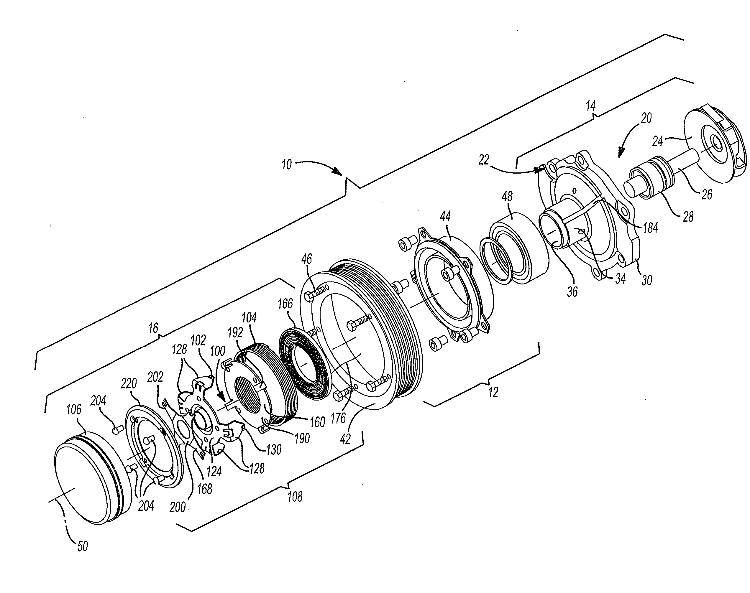
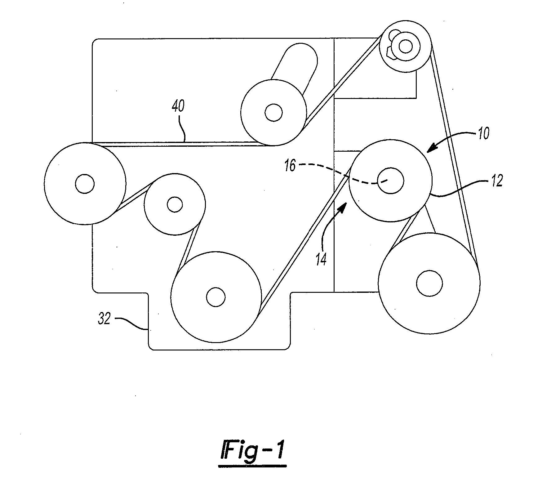
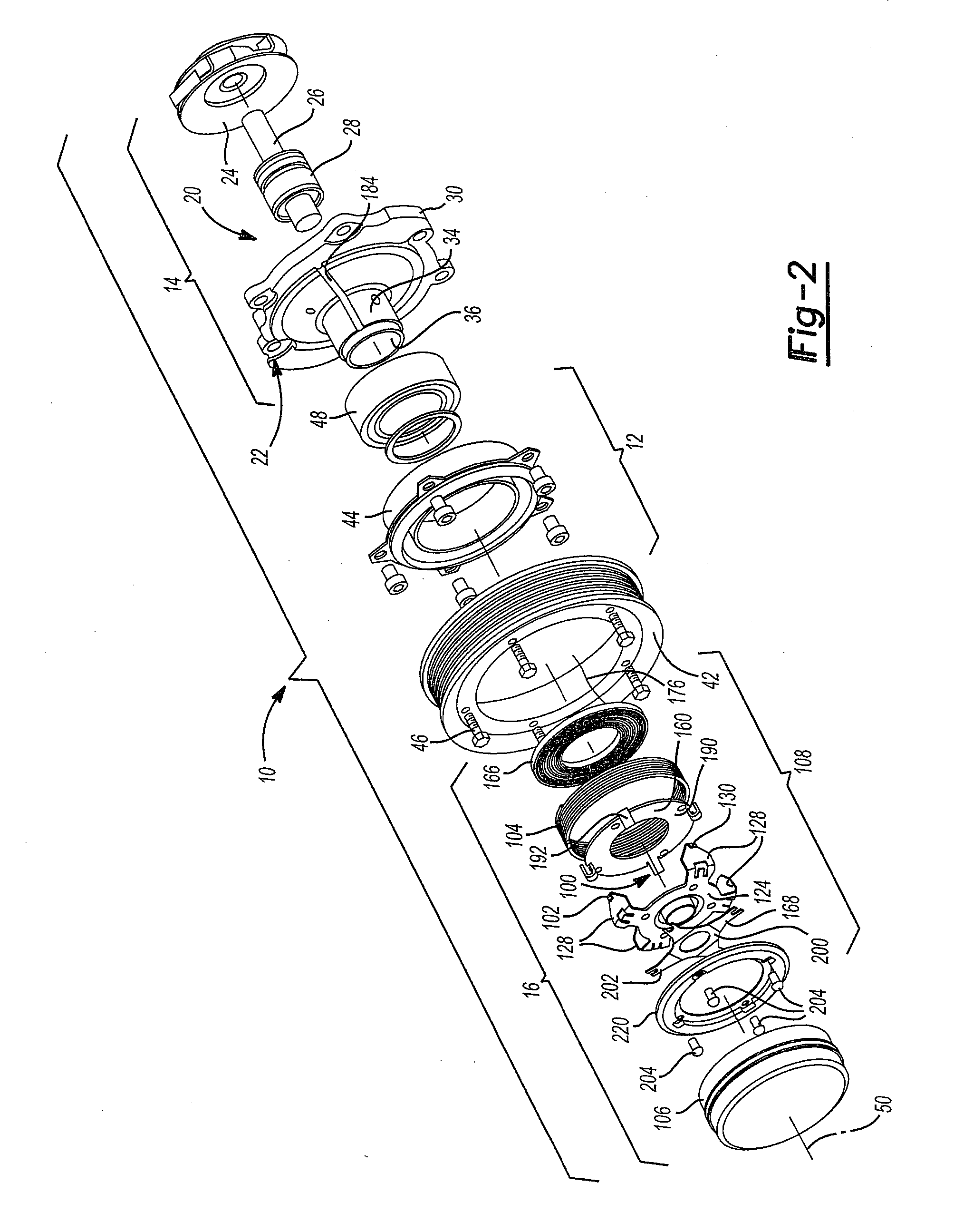
[0072]With reference to FIGS. 1 and 2 of the drawings, a driven accessory constructed in accordance with the teachings of the present disclosure is generally indicated by reference numeral 10. The driven accessory 10 can comprise an input member 12, a substantially conventional accessory portion 14 and a clutch assembly 16. In the particular example provided, the accessory portion 14 is a water pump assembly 20, but those of skill in the art will appreciate that the depiction of a water pump assembly 20 is merely illustrative of one application of the present teachings and that the present teachings have application to various other types of engine accessories, such as cooling fans 14-1 (FIG. 26); starter-generators or alternator-starters 14-2 (FIG. 27); air conditioning compressors 14-3 (FIG. 28); power steering pumps 14-4 (FIG. 29); generators or alternators 14-5 (FIG. 30); pumps including vacuum pumps 14-6 (FIG. 31), blowers, super chargers, power take-offs, etc., as well as acce...


PUM


Abstract

A driven accessory having a clutch that permits selective operation of an accessory portion. The clutch employs rotational inertia to control driving engagement of a wrap spring to an interior clutch surface on a drive member and/or driving disengagement of the wrap spring from the interior clutch surface.

Description

CROSS-REFERENCE TO RELATED APPLICATIONS[0001]This application is a continuation-in-part of U.S. application Ser. No. 12 / 620,023 filed Nov. 17, 2009, which claims the benefit of U.S. Provisional Patent Application No. 61 / 115,223 filed Nov. 17, 2008, U.S. Provisional Patent Application No. 61 / 159,608 filed Mar. 12, 2009 and U.S. Provisional Patent Application No. 61 / 229,385 filed Jul. 29, 2009. The disclosures of each of the above-referenced applications is incorporated by reference as if fully set forth in detail herein.INTRODUCTION[0002]The present disclosure relates to a driven accessory with a low-power clutch for activating or deactivating the driven accessory.[0003]Most vehicle engine systems include one or more driven devices, typically referred to as “accessories”, which are driven by the vehicle engine for a variety of purposes. Such accessories can be connected to the engine via an accessory drive, a timing drive, etc. which can comprise a belt drive (e.g., a drive that empl...

Claims


Application Information

Patent Timeline
Patent Type & Authority Applications(United States)
IPC IPC(8): F16D13/00F16D13/12F16D13/38F16D27/00
CPCB60K25/02F16D27/105Y02T10/76F16D2027/002F16D27/112F16D27/14B60K25/00F02B67/06
Inventor PARSONS, SCOTTBOYES, ANDREWVANDER PLOEG, CHRISTIAAN
Owner LITENS AUTOMOTIVE INC
Why Eureka
Try Eureka