Lighting activation systems and methods

a technology of lighting activation and system, applied in the field of lighting activation system and method, can solve the problems of inconvenient or problematic fixed location of wall-mounted switch or switch, difficulty in finding light switch, difficulty in finding light switch, etc., and achieve the effect of reducing power consumption

Inactive Publication Date: 2010-09-16
MEO MIO
View PDF32 Cites 29 Cited by
  • Summary
  • Abstract
  • Description
  • Claims
  • Application Information

AI Technical Summary

Benefits of technology

[0007]In accordance with one embodiment of this invention, a system and method for activating remote lights is provided in connection with a floor cover member such as a rug or mat having pressure switch means that activates a radio frequency (RF) transmitter on board when a user steps onto the floor cover member. The system further preferably comprises at least one remote light containing a corresponding RF receiver, such that the remote light is turned on when a signal from the RF transmitter is received. Most preferably, the remote lights, the transmitter and the floor cover member are battery powered, such that placement is not limited to locations with access to power outlets. The transmitter and receivers preferably operate in pulse or periodic sleep mode to reduce power consumption.

Problems solved by technology

Often the fixed location of the wall-mounted switch or switches is inconvenient or problematic based on factors like the physical condition of the user and the conditions in the environment of use.
For example, a child will have difficulty finding a light switch at night should he or she need to go to the bathroom, become scared or choose to leave his or her bed for other reasons.
Likewise, an elderly person may be disoriented when arising in the dark such that finding a light switch may be difficult.
Even where sufficient light may be available to locate the switch, a disabled individual may have difficulty physically reaching the switch location.

Method used


Image

  • Lighting activation systems and methods
  • Lighting activation systems and methods
  • Lighting activation systems and methods

Examples


Embodiment Construction

[0021]The invention and its various embodiments will now be described with reference to the drawings.

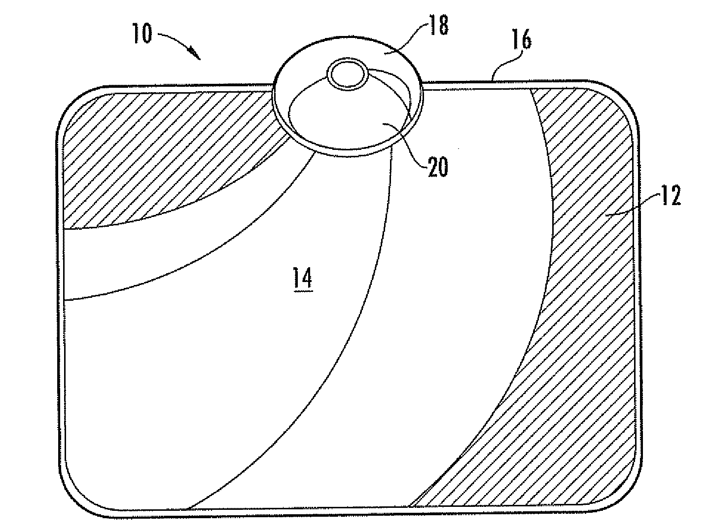
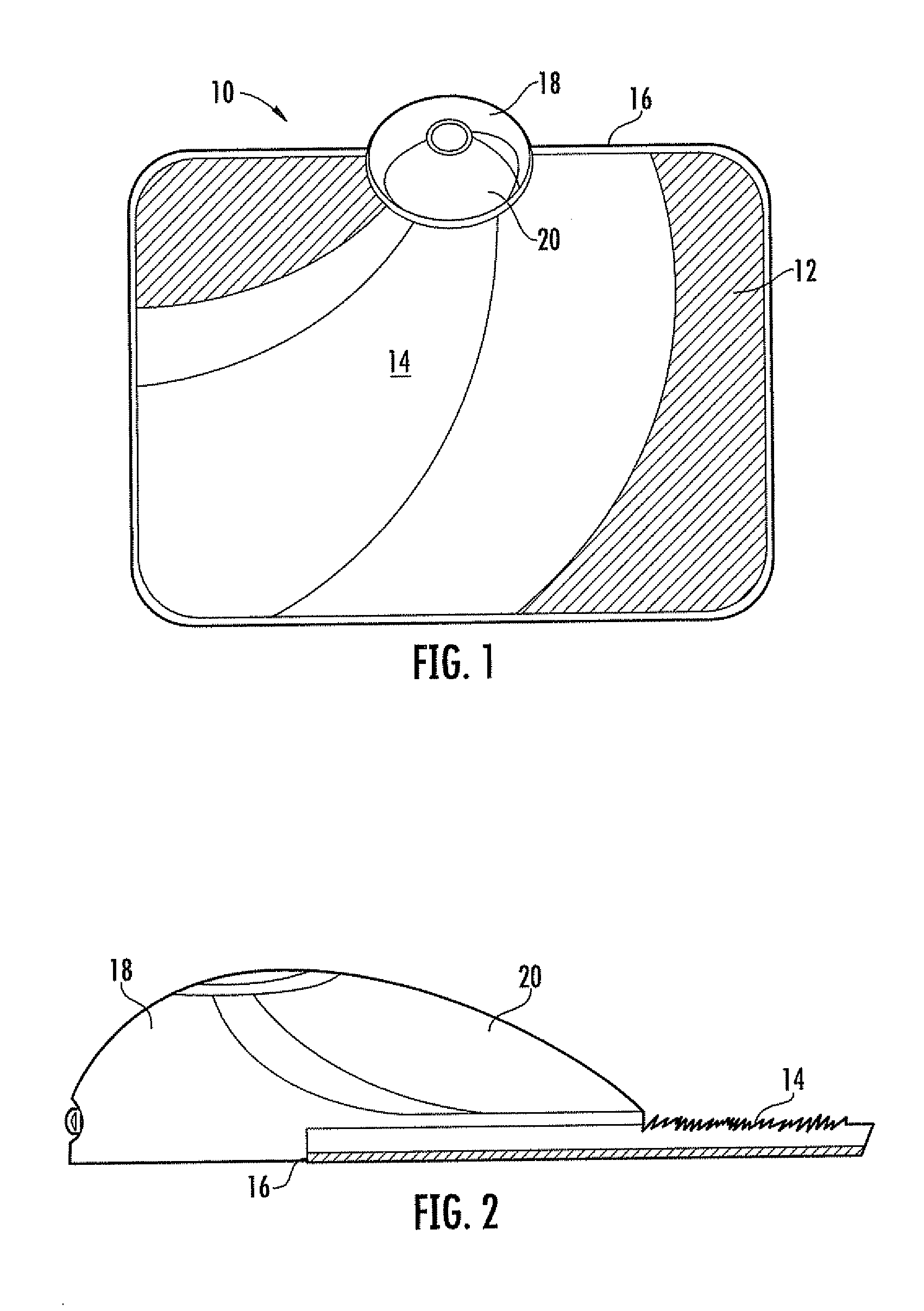
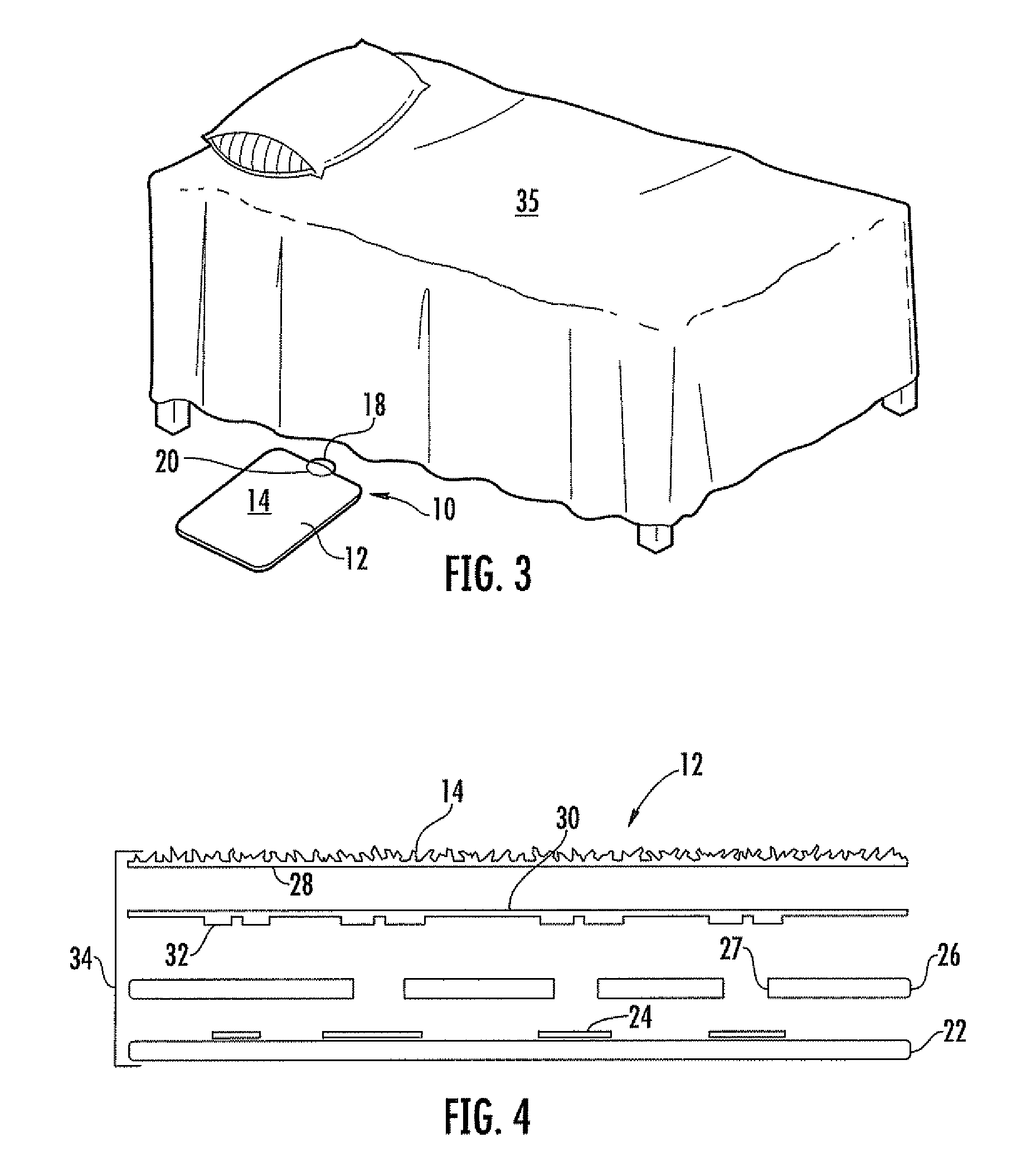
[0022]In a first embodiment shown in FIGS. 1-8, the invention comprises a light system 10 with a floor cover member 12 preferably in the form of a rug or mat sized to be positioned next to a bed as shown in FIG. 3, along a hallway or in a doorway, at the top or bottom of stairs or any other location as desired for its purpose, which is to provide a low level light by applying pressure on the top surface 14 of the member 12 without the need for searching for a wall-mounted light switch or a lamp switch in the dark and using only battery power. Preferably, the floor cover member 12 incorporates a light 20 within a light housing 18 embodied in or attached to the floor cover member 12, such that lighting is provided when a user steps out of bed, into a hallway or under similar circumstances thereby activating the light 20. In this embodiment, the housing 18 is positioned along the periph...


PUM


Abstract

A system and method for activating one or more lights or other devices using one or more activation devices including electronic circuitry. The electronic circuitry of the activation devices includes an activation sensor, based on which the lights or other devices are activated. Activation sensors include motion, sound or light sensors. With transmitters the activation devices can activate remote lights or other devices including receivers. Activation devices can be coupled with or apart form the lights or other devices.

Description

CROSS-REFERENCE TO RELATED APPLICATION[0001]This application claims the benefit of U.S. Provisional Application Ser. No. 60 / 998,210, filed on Oct. 9, 2007, the contents of which are hereby incorporated by reference in their entirety.FIELD OF THE INVENTION[0002]This invention and its various embodiments relate generally to systems and methods for activating lighting, and more particularly relate to systems that can be activated by one or more pressure switches.BACKGROUND OF THE INVENTION[0003]It is well known in the prior art to utilize an individual light or sets of lights that are operated by a wall-mounted switch or a switch incorporated into a stand-alone lamp. Often the fixed location of the wall-mounted switch or switches is inconvenient or problematic based on factors like the physical condition of the user and the conditions in the environment of use. For example, a child will have difficulty finding a light switch at night should he or she need to go to the bathroom, become ...

Claims


Application Information

Patent Timeline
Patent Type & Authority Applications(United States)
IPC IPC(8): G08B21/00
CPCA47G27/0225E04F2290/026A47L9/30A47G27/0243
Inventor VON MOHR, PAUL J.WYMAN, DENNISWILLIAMS, MARK
Owner MEO MIO
Why Eureka
Try Eureka