Quantitative phase-contrast and excitation-emission systems

a phase contrast and excitation emission technology, applied in the field of optical systems, can solve the problems of limited capacity to effectively observe transparent samples, limited capacity to quantify or even observe these processes,

Inactive Publication Date: 2010-09-16
UT BATTELLE LLC
View PDF16 Cites 16 Cited by
  • Summary
  • Abstract
  • Description
  • Claims
  • Application Information

AI Technical Summary

Problems solved by technology

To quantify or even observe these processes is limited by some bright-field microscopes.
Others have limited capability

Method used


Image

  • Quantitative phase-contrast and excitation-emission systems
  • Quantitative phase-contrast and excitation-emission systems
  • Quantitative phase-contrast and excitation-emission systems

Examples


Embodiment Construction

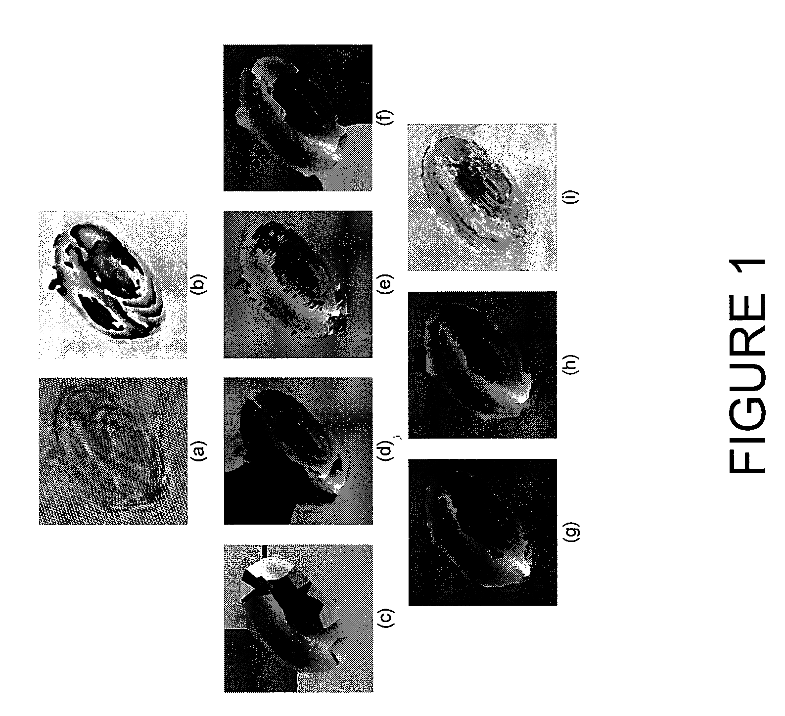
[0015]Quantifying optical path length changes may detect refractive indexes or optical thickness variations with a vertical resolution of a few nanometers. The quantification may be used to investigate morphological variations associated with dynamic biological processes, such as drug delivery, disease progression, and / or other pathological occurrences.

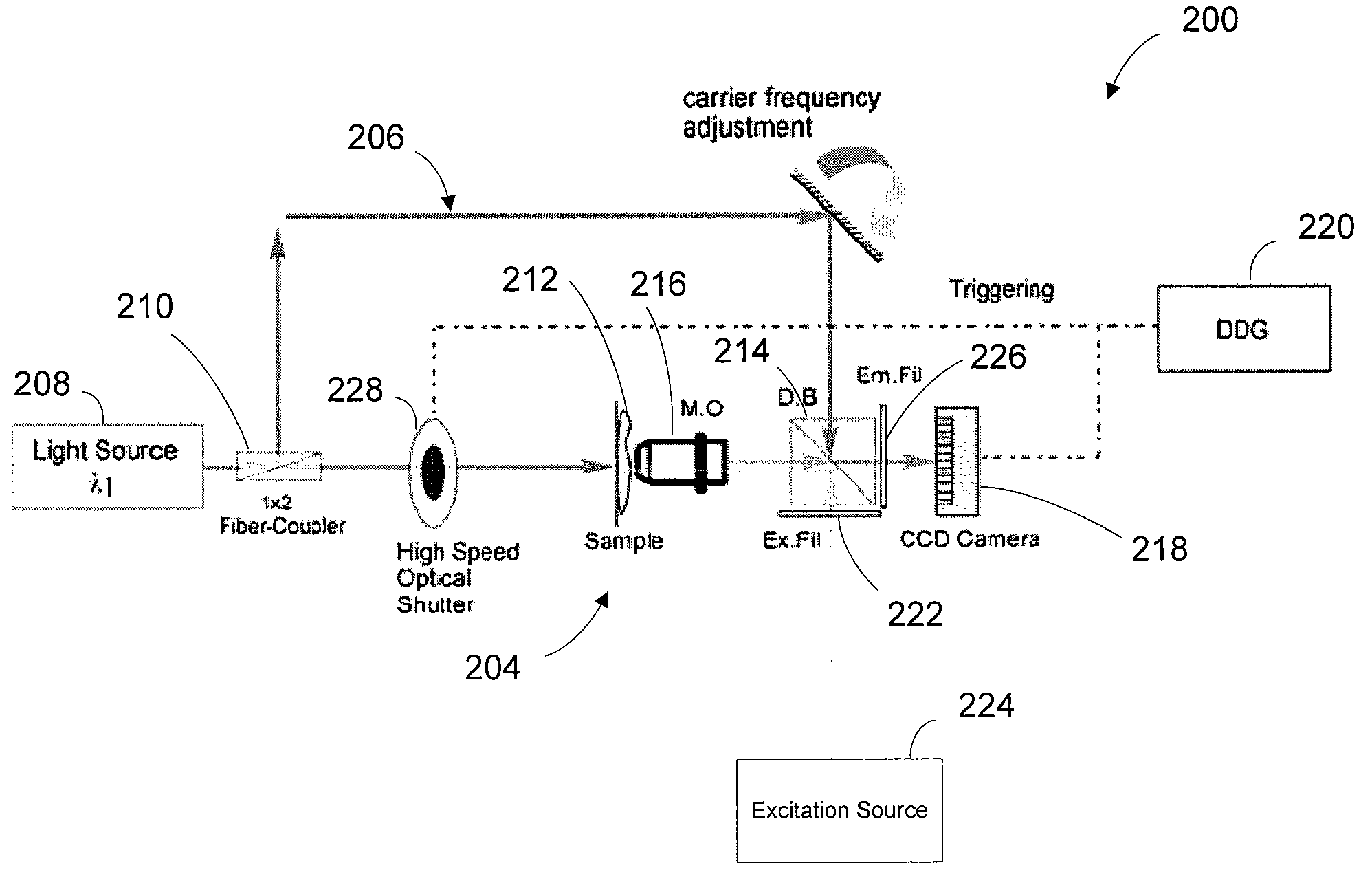
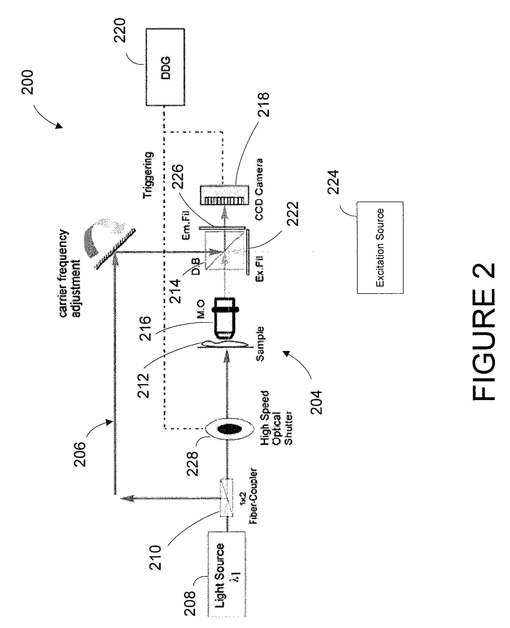
[0016]Unlike some phase-shifting systems, an optical system may include one or more digital optical interferometers that may not require multiple image acquisitions or phase modulations. The data or information in a complete volume may be recorded in a single digital image within a local or a remote memory or database that facilitates real-time imaging and viewing (e.g., through a display) locally or at a remote site. The speed of the image capture may depend on the frame rate of capture of an interfaced recording device or latency in which the data is stored or written into the local and / or remote memory. The magnification may differ...


PUM


Abstract

An optical system includes an optical interferometer that generates interference phenomena between optical waves to measure multiple distances, thicknesses, and indices of refraction of a sample. An excitation-emission device allows an electromagnetic excitation and emission to pass through an objective in optical communication with the sample. An electromagnetic detector receives the output of the optical interferometer and the excitation-emission device to render a magnified image of the sample. A digital delay generator synchronizes the optical interferometer and excitation-emission device to operate in substantially unison to generate a noninvasive depth of field of the portion of the sample that corrects a plurality of optical aberrations in real-time.

Description

RELATED APPLICATION [0001]This application is related to U.S. application Ser. No. ______ (Attorney Docket No. 13489 / 80 (ID 2154)) filed on Mar. 16, 2009, entitled “Quantitative Phase-Imaging Systems,” and U.S. application Ser. No. ______ (Attorney Docket No. 13489 / 95 (ID 2150.0)) filed on Mar. 16, 2009, entitled “Three Wavelength Quantitative Imaging Systems,” which are incorporated by reference.BACKGROUND OF THE INVENTION[0002]1. Technical Field[0003]This disclosure relates to optical systems and particularly to systems that apply transmissive and reflective magnifications.[0004]2. Related Art[0005]Biological processes and structures of transparent objects are of interest in the life science fields. To quantify or even observe these processes is limited by some bright-field microscopes. Some microscopes have small depths of focus at high lateral magnifications. Others have limited capability to effectively observe transparent samples such as living biological cells which exhibit v...

Claims


Application Information

Patent Timeline
IPC IPC(8): G01B9/021G01N21/63
CPCG01B9/021G01B11/0675G02B21/0056G01N21/4133G01B11/2441
Inventor MANN, CHRISTOPHER J.BINGHAM, PHILIP R.
Owner UT BATTELLE LLC
Why Eureka
Try Eureka