
Cylindrical measuring head and measuring method for small gear measurement

A technology of gear measurement and measurement method, applied in the direction of measuring devices, instruments, etc., can solve the problems of poor stiffness of the measuring rod, difficulty in measurement, and inability to measure, so as to improve the measurement efficiency, improve the mechanical precision, and optimize the mechanical structure.

Inactive Publication Date: 2017-04-05
HARBIN JINGDA MEASURING INSTR
View PDF7 Cites 13 Cited by
  • Summary
  • Abstract
  • Description
  • Claims
  • Application Information

AI Technical Summary

Problems solved by technology

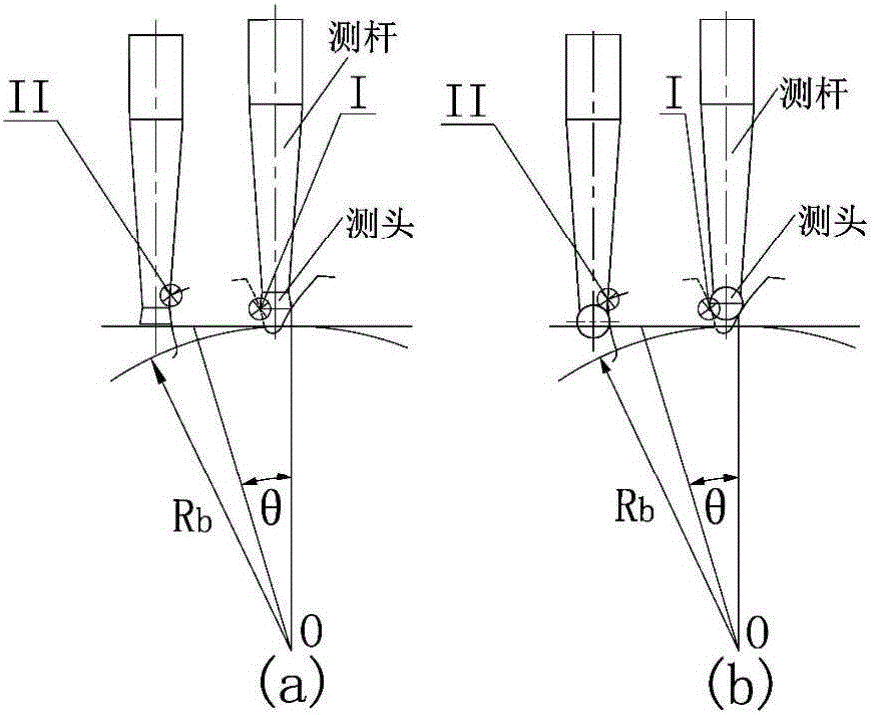
[0006] However, if figure 2 As shown in a and b, 1) For tiny modulus gears, it is difficult to enter the root of the tooth profile for measurement due to the small gap between the teeth and the influence of the diameter of the probe
2) During the measurement process, the measuring rod will interfere with the tooth surface
In order to avoid this phenomenon, the diameter of the measuring head rod should be smaller than the diameter of the measuring ball or the diameter of the inverted cone, which not only makes the stiffness of the measuring rod worse, but also increases the difficulty of manufacturing the measuring head, so that the measurement accuracy cannot be guaranteed, or even completely Unable to measure

Method used


Image

  • Cylindrical measuring head and measuring method for small gear measurement
  • Cylindrical measuring head and measuring method for small gear measurement
  • Cylindrical measuring head and measuring method for small gear measurement

Examples


specific Embodiment approach

[0028] refer to Figure 7 , the present invention provides a new control method for the involute measurement track, the method is different from the traditional spherical and inverted cone measuring probe used in the existing micro-gear measuring instrument to implement the measurement of the new cylindrical probe.

[0029] refer to Figure 6 The measuring head used in the control method of the involute measuring track of the present invention is composed of a measuring rod 1 and a cylindrical measuring needle 2 embedded in the front end of the measuring rod. The needle tip of the measuring needle is ground into a circle perpendicular to the axis of the measuring needle. Shaped end face, the stylus is made of high-hardness tungsten steel cylindrical profile, which can effectively improve the stiffness of the stylus.

[0030] The method for measuring tiny gears by applying the control method of the above-mentioned involute measurement trajectory is composed of the following st...


PUM

PropertyMeasurementUnit
Modulusaaaaaaaaaa

Abstract

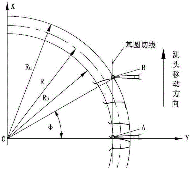
A cylindrical measuring head and measuring method for small gear measurement are provided. Technical points are that joint control of three coordinate axes X, Y, [phi] is achieved along the meshing line direction of a gear and simultaneous motion is achieved according to a proportional relation formed by the principle of meshing line. The measuring method comprises: firstly installing the gear on a gear measuring center rotary shaft, and then enabling the measuring rod mounting direction of the measuring head to be parallel with the Y-axis direction of the gear measuring center, wherein the measurement starting position of a measuring needle is a gear root measurement starting point; in accordance with the generation principle of gear meshing line, controlling the measuring head to synchronously move along the X, Y axes, and at the same time, revolving the gear around the [phi] axis, and enabling the measuring needle to move to a measurement finish position along the meshing line direction of a tooth crest along with the tooth surface of the gear. The sensing error of the tangential measuring head is the tooth profile error of the gear. The method avoids a case that in a traditional measurement method, because the gear tooth groove is small, the measuring head cannot enter the gear root measurement starting point and the measuring rod and the tooth surface have an unnecessary interference phenomenon in a measurement process.

Description

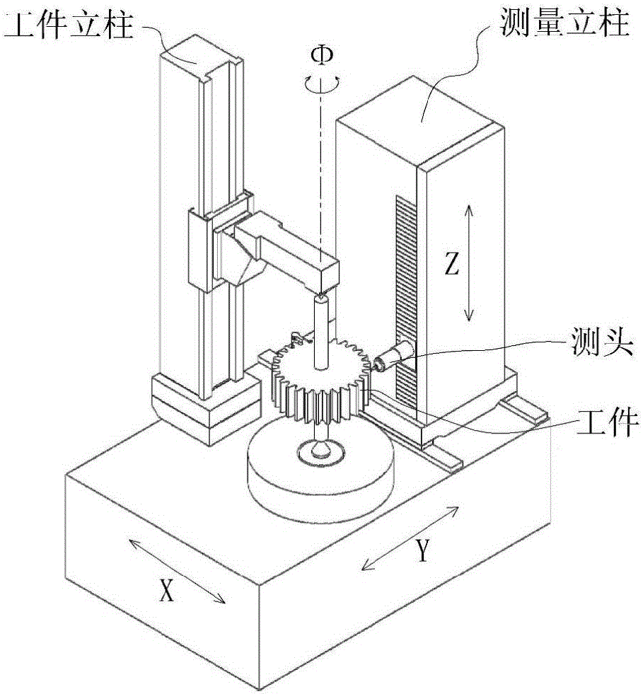
Technical field: [0001] The invention relates to the field of measurement of gear precision instruments, in particular to a cylindrical measuring head and a measurement method for solving the measurement of tiny modulus gears. Background technique: [0002] The gear measurement center is composed of mechanical system, numerical control system, data acquisition system and measurement software. It can realize the four-axis linkage of X, Y, Z axis directions and the rotation axis Φ axis, and can measure cylindrical gears of different structures and shapes and various tools. , such as bevel gears, worm gears, worms, hobs, shaving cutters, gear shaping cutters, and compressor rotors, etc., are mainly used for the detection of single geometric accuracy of gears. The measurement accuracy of the gear measurement center mainly depends on the accuracy of sensors such as probes and gratings and the guidance accuracy of 4 relatively independent guide structures (3 linear guides and 1 ma...

Claims


Application Information

Patent Timeline
IPC IPC(8): G01B21/00
CPCG01B21/00
Inventor 周广才李晓杰刘丽雪
Owner HARBIN JINGDA MEASURING INSTR
Learn More