Photosynthesis inhibiting light source and illuminating device that uses the same
a technology of light source and illuminating device, which is applied in the direction of semiconductor devices for light sources, discharge tubes luminescnet screens, lighting and heating apparatus, etc. it can solve the problems of destroying the ecosystem in the cave, physical means and chemical means will damage the wall surface of the cave, and the inability to illuminate the inside of the cave, etc., to inhibit/stun the growth and propagation of photosynthetic organisms, inhibit/stun the growth and propagation of photosynthetic organism
- Summary
- Abstract
- Description
- Claims
- Application Information
AI Technical Summary
Benefits of technology
Problems solved by technology
Method used
Image

Examples
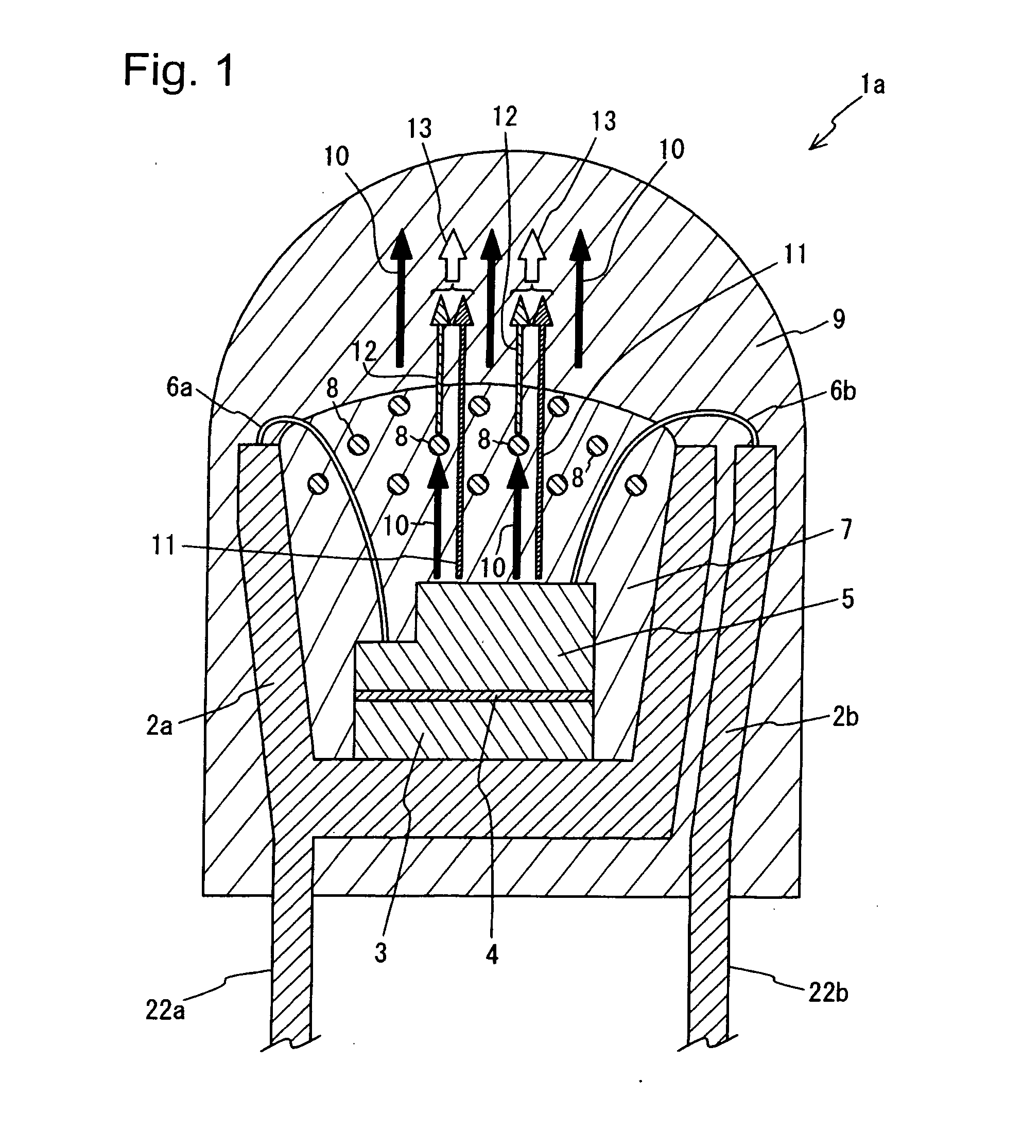
embodiment 1
[0105]As described above, until now, from various experiments and researches, it has been known that both blue light having a light emission peak in wavelengths of 430 to 490 nanometers (nm) and red light having a light emission peak in wavelengths of 640 to 680 nm, in more detail, both blue light having a light emission peak in wavelengths of 430 to 490 nm and orange-to-red light having a light emission peak in wavelengths of 600 to 680 nm are required to allow photosynthetic organisms to grow normally.
[0106]Additionally, it has been known from various experiments and researches that red light having a light emission peak in wavelengths of 640 to 680 nm, in more detail, orange-to-red light having a light emission peak in wavelengths of 600 to 680 nm is required especially when photosynthesis is carried out inside the body of a photosynthetic organism.
[0107]Therefore, the present inventors have found that the normal growth of photosynthetic organisms can be stunted by mixing and emi...
embodiment 2
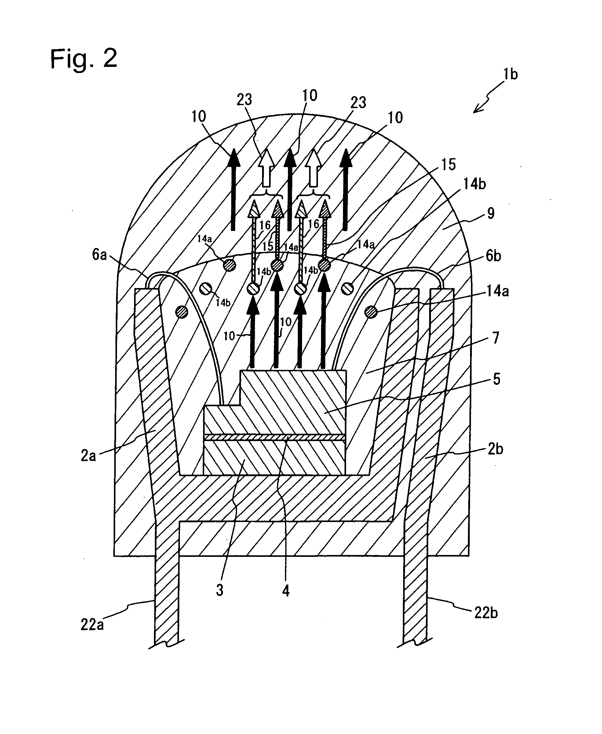
[0141]Next, the photosynthesis inhibiting light source according to the second embodiment of the present invention will be described in detail with reference to FIG. 2.
[0142]FIG. 2 is a sectional view of the photosynthesis inhibiting light source according to the second embodiment of the present invention. The same numeral is given to the same component as in FIG. 1, and a description of its structure is omitted. The photosynthesis inhibiting light source 1b according to the second embodiment is substantially the same in structure as the photosynthesis inhibiting light source 1a according to the first embodiment mentioned above, and, in the second embodiment, a description will be given with emphasis on differences with the photosynthesis inhibiting light source 1a according to the first embodiment.
[0143]As shown in FIG. 2, the photosynthesis inhibiting light source 1b according to the second embodiment is characterized by including two kinds of fluorescent substances 14a and 14b in...
embodiment 3
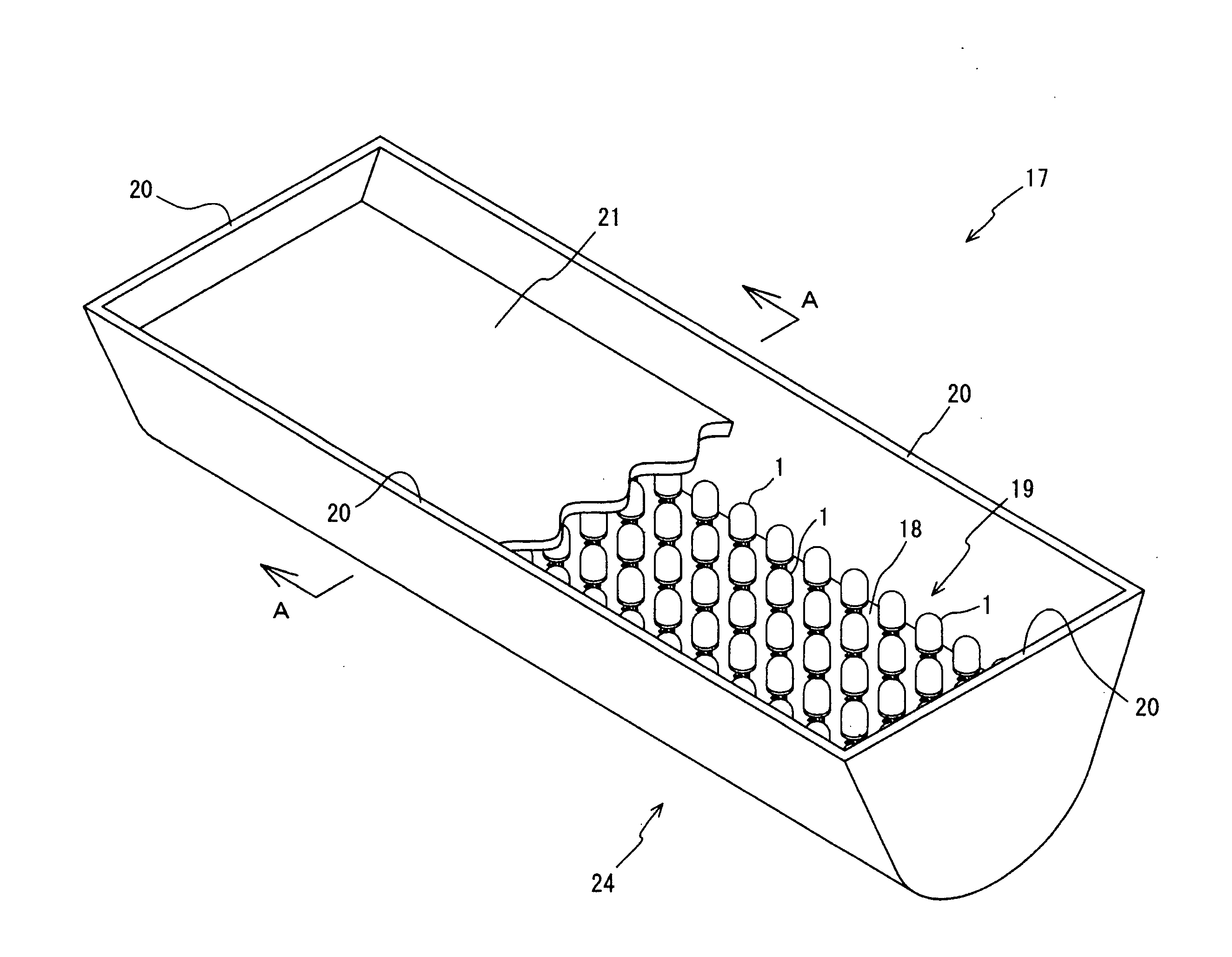
[0151]Lastly, the photosynthesis inhibiting illuminating device according to the third embodiment of the present invention will be described in detail with reference to FIG. 3 and FIG. 4.
[0152]FIG. 3 is a conceptual diagram of the photosynthesis inhibiting illuminating device according to the third embodiment of the present invention, and FIG. 4 is a sectional view along line A-A of FIG. 3. The same numeral is given to the same component as in FIGS. 1 and 2, and a description of its structure is omitted.
[0153]The photosynthesis inhibiting illuminating device according to the third embodiment uses the photosynthesis inhibiting light sources 1a and 1b according to the first and second embodiments, and the photosynthesis inhibiting light sources 1a and 1b are represented generically as the photosynthesis inhibiting light source 1 in FIG. 3.
[0154]As shown in FIGS. 3 and 4, the photosynthesis inhibiting illuminating device 17 according to the third embodiment is structured such that a pl...
PUM
 Abstract
Description
Claims
Application Information
 - R&D
- Intellectual Property
- Life Sciences
- Materials
- Tech Scout
- Unparalleled Data Quality
- Higher Quality Content
- 60% Fewer Hallucinations
Browse by: Latest US Patents, China's latest patents, Technical Efficacy Thesaurus, Application Domain, Technology Topic, Popular Technical Reports.
© 2025 PatSnap. All rights reserved.Legal|Privacy policy|Modern Slavery Act Transparency Statement|Sitemap|About US| Contact US: help@patsnap.com