DC converter

a converter and dc technology, applied in the direction of dc-dc conversion, power conversion systems, climate sustainability, etc., can solve the problems of inability to set such a high level of frequency at rated load, cross regulation becomes worse, etc., to prevent the increase of frequency at no load, small, inexpensive, and high-efficiency dc

Active Publication Date: 2010-09-16
SANKEN ELECTRIC CO LTD
View PDF6 Cites 11 Cited by
  • Summary
  • Abstract
  • Description
  • Claims
  • Application Information

AI Technical Summary

Benefits of technology

[0033]It is an object of the present invention to provide a small, inexpensive, and high-efficiency DC converter capable of preventing a frequency at no load from increasing.
[0042]According to the first aspect of the present invention, since the capacitive element is connected to the current resonant reactor in parallel, the current passes through the capacitive element, and the floating capacitance equivalently present between the primary winding of the transformer is charged and discharged without passing a current through the current resonant reactor. Thus, it is possible to provide a small, inexpensive, and high-efficiency DC converter capable of preventing a frequency at no load from increasing.

Problems solved by technology

Meanwhile, when the DC converter is configured to have a multi-output configuration, a cross regulation becomes worse under a combined load condition of no load (light load) in one side and heavy load in the other side.
However, since the frequency increases over the theoretical value, the frequency at rated load cannot be set at such a high level under present circumstances.

Method used


Image

  • DC converter
  • DC converter
  • DC converter

Examples


example 1

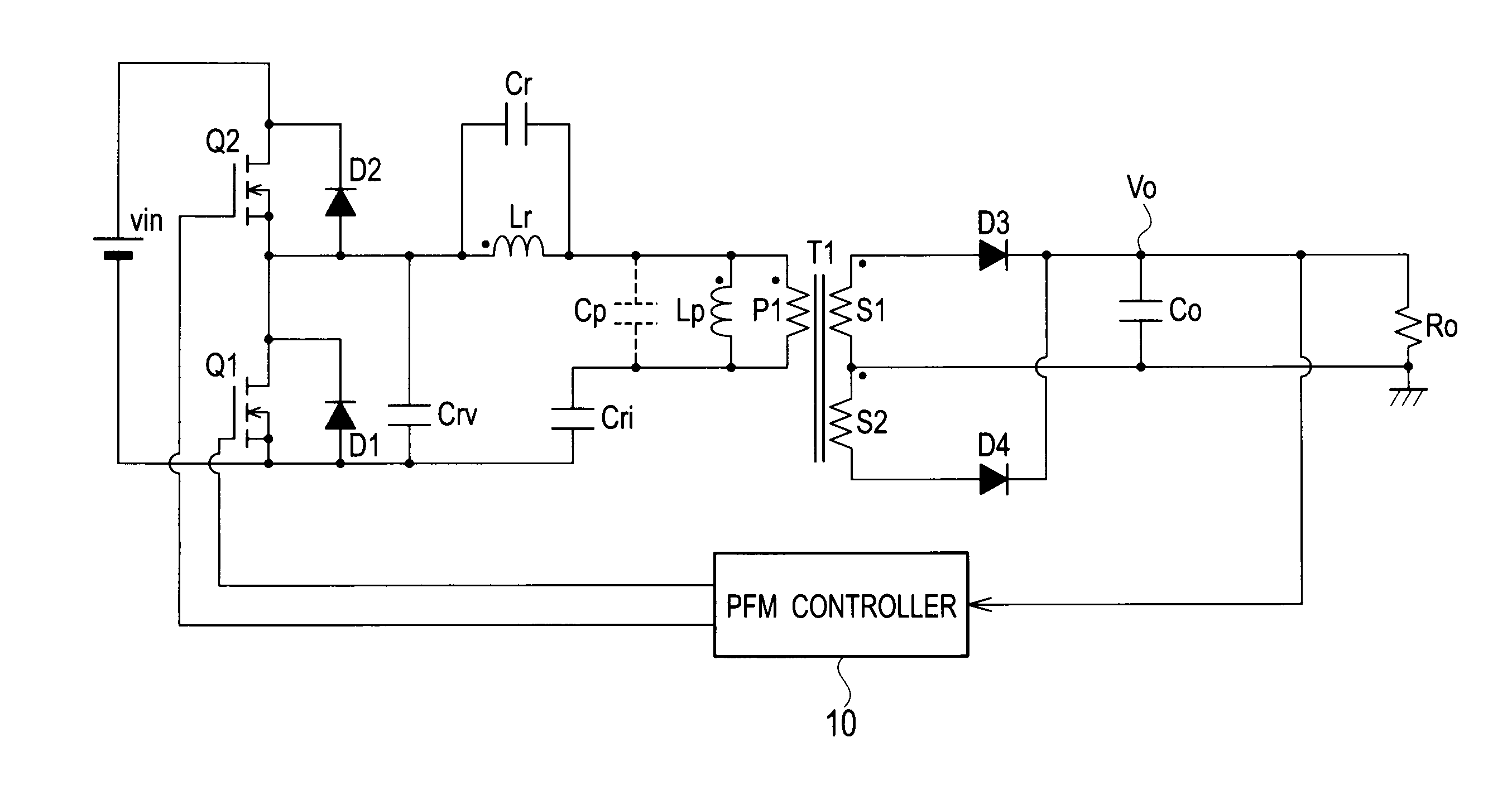
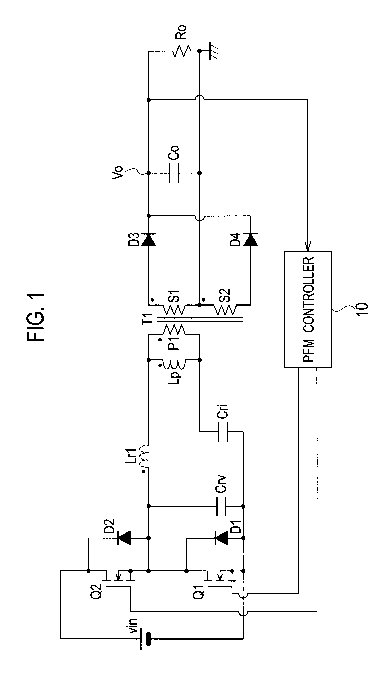
[0061]In Example 1 illustrated in FIG. 8, in order to bypass a charge amount corresponding to charge and discharge of the floating capacitance Cp equivalently present between the primary winding P1 of the transformer T1, a capacitor Cr (capacitive element) connected to a current resonant reactor Lr in parallel is provided. Thus, charge and discharge energy of the parasitic capacitances of the diodes D3 and D4 has been configured not to be stored in the current resonant reactor Lr. That means the capacitor Cr is connected to the current resonant reactor Lr in parallel, whereby a current due to charge and discharge of the floating capacitance Cp between the primary winding P1 of the transformer T1 has been configured not to pass through the current resonant reactor Lr.

[0062]In Example 1 illustrated in FIG. 8, a series resonant circuit composed of the current resonant reactor Lr, the primary winding P1 of the transformer T1, and the current resonant capacitor Cri is connected to the sw...

example 2

[0070]FIG. 11 is a circuit configuration diagram of a DC converter in Example 2 of the present invention. The floating capacitance Cp between the primary winding P1 of the transformer T1 includes a resistance component in series. Therefore, Example 2 can be represented by an equivalent circuit, which is composed of a series circuit of the floating capacitance Cp and a resistance Rp as illustrated in FIG. 11.

[0071]Thus, as illustrated in FIG. 11, the circuit configuration, in which a series circuit of the capacitor Cr and a resistor Rr is connected to the current resonant reactor Lr in parallel while corresponding to the series circuit of the floating capacitance Cp and the resistance Rp, is appropriate as the actual circuit configuration.

[0072]In Example 2 illustrated in FIG. 11, similar to Example 1, an influence of the reactor Lp can be cancelled by setting the capacitor Cr and the resistor Rr to meet the following formulae,

Cr=LpLr·Cp,Rr=LrLp·Rp.[Math3]

[0073]That means the value o...

example 3

[0075]FIG. 12 is a circuit configuration diagram of a DC converter in Example 3 of the present invention. In Example 3 illustrated in FIG. 12, compared to Example 2 illustrated in FIG. 11, a transformer T2 including the primary winding P1 and the secondary winding S1 is provided while removing the secondary winding S2 and the diode D4, and a PRC controller 11 is employed.

[0076]The PRC controller 11 fixes an on-time of one switching element Q1 (or Q2), and varies an ontime of the other switching element Q2 (or Q1). Thus, a DC output voltage Vo is controlled. Note that, both of the switching elements Q1 and Q2 have a dead time that is in an off state of both of the switching elements Q1 and Q2 simultaneously.

[0077]According to such a configuration, when the switching element Q2 is an on state, a current passes through the capacitor Co via the diode D3 from the secondary winding S1 of the transformer T2. Accordingly, power is applied to a load Ro. While, when the switching element Q1 i...


PUM


Abstract

A DC converter includes: a transformer (T1) including a primary winding (P1) and a secondary winding (S1); a series resonant circuit in which a current resonant reactor (Lr), the primary winding (P1) of the transformer, and a current resonant capacitor (Cri) are connected in series; conversion circuits (Q1, Q2) for converting a DC voltage of a DC power supply (Vin) into a rectangular-wave voltage, so as to output the rectangular-wave voltage to the series resonant circuit; and a rectifier smoothing circuit (D3, D4, Co) for rectifying and smoothing a voltage generated at the secondary winding (S1) of the transformer, so as to output a DC output voltage to a load, wherein a capacitive element (Cr) including a capacitive component corresponding to a floating capacitance (Cp) equivalently present between the primary winding of the transformer was connected to the current resonant reactor (Lr) in parallel.

Description

TECHNICAL FIELD[0001]The present invention relates to a DC converter that is highly efficient, small in size and inexpensive.BACKGROUND ART[0002]FIG. 1 illustrates a circuit configuration diagram of a conventional DC converter (PLT 1). This DC converter is composed of a half-bridge circuit, in which a series circuit including switching elements Q1 and Q2 consisting of MOSFETs is connected to both ends of a DC power supply Vin. A drain of the switching element Q2 is connected to a positive electrode of the DC power supply Vin and a source of the switching element Q1 is connected to a negative electrode of the DC power supply Vin.[0003]Between the drain and source of the switching element Q1, a diode D1 and a voltage resonant capacitor Cry are connected in parallel. In addition, a reactor Lr1, a primary winding P1 of a transformer T1, and a current resonant capacitor Cri are connected in series. The reactor Lr1 is a leakage inductance between the primary and secondary sides of the tra...

Claims


Application Information

Patent Timeline
Patent Type & Authority Applications(United States)
IPC IPC(8): H02M3/335
CPCY02B70/1433H02M3/3378Y02B70/10
Inventor ASO, SHINJI
Owner SANKEN ELECTRIC CO LTD
Why Eureka
Try Eureka