Communication system, communication method, radio terminal, radio relay device, and control device

Active Publication Date: 2010-09-16
PANASONIC INTELLECTUAL PROPERTY CORP OF AMERICA
View PDF11 Cites 22 Cited by
  • Summary
  • Abstract
  • Description
  • Claims
  • Application Information

AI Technical Summary

Benefits of technology

[0079]The present invention provides such effects that there is no need to transmit all of the packets transmitted from the transmitting side radio terminal between the radio relay device and the control device, and partial data or small amount of data would be sufficient. Thus, network resources of the radio relay device and the control device

Problems solved by technology

ACGW 105 performs communication with a multiple of UEs, and the processing to decrypt the packets from UE and the processing to encrypt the packet to be trans

Method used


Image

  • Communication system, communication method, radio terminal, radio relay device, and control device
  • Communication system, communication method, radio terminal, radio relay device, and control device
  • Communication system, communication method, radio terminal, radio relay device, and control device

Examples


first embodiment

The First Embodiment

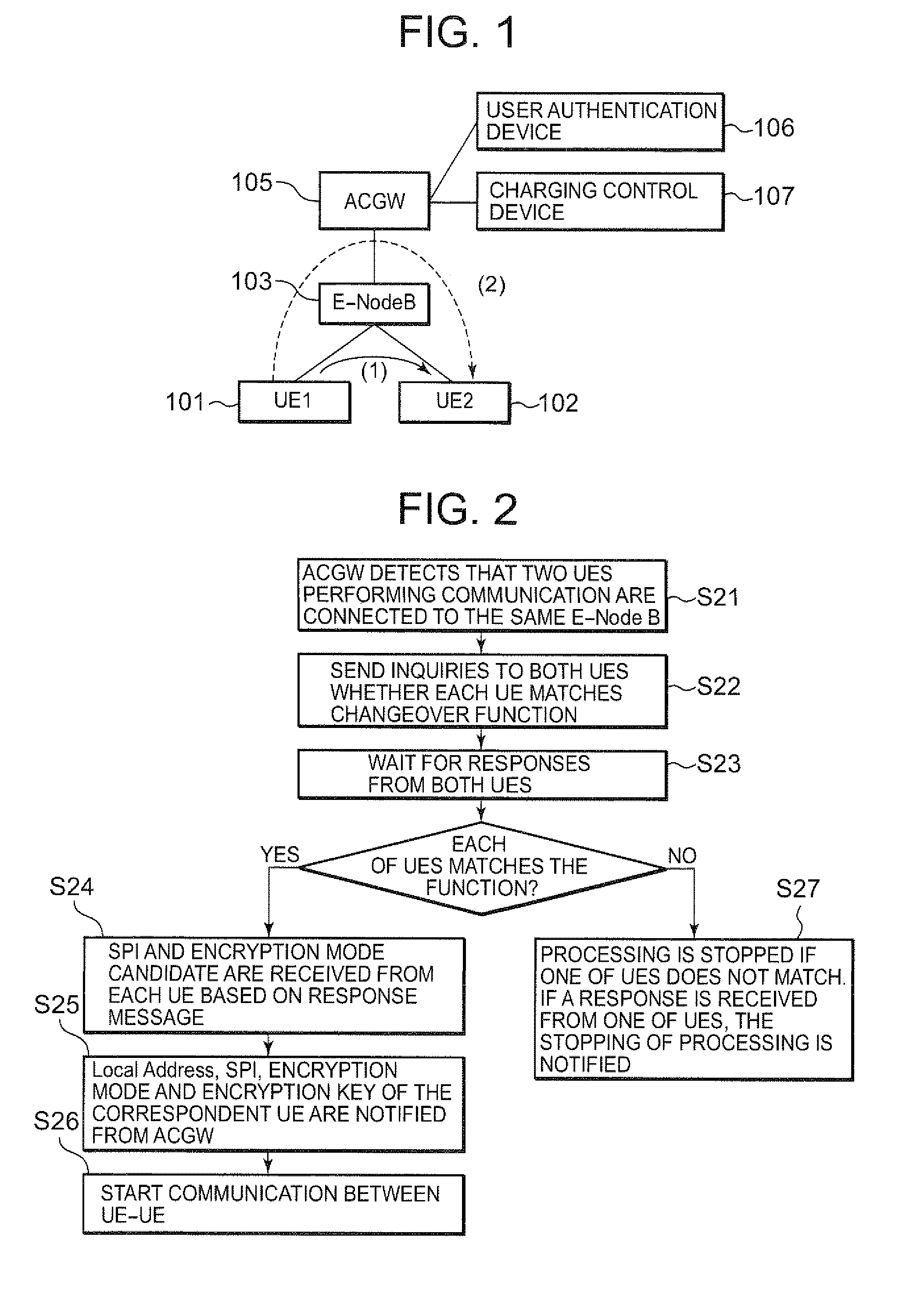
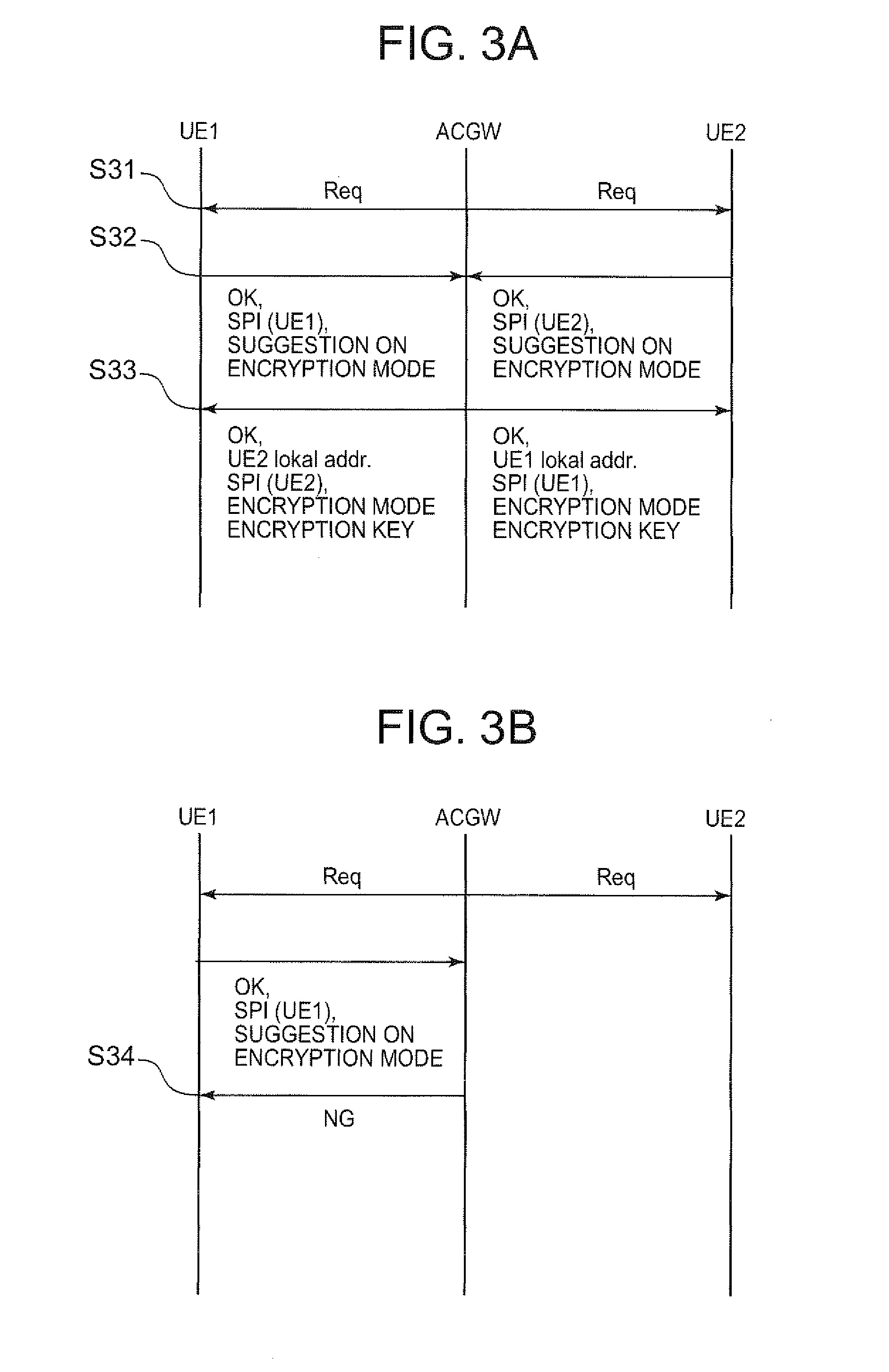
[0114]Description will be given below on the embodiment of the invention by referring to the attached drawings. FIG. 1 shows a condition where UE 101 and UE 102 are connected to the same base station (hereinafter, referred as “E-Node B”). This condition includes a case where the condition is continuously present from the moment of the starting of the communication and a case where UE 101 or UE 102 moves from the condition shown in FIG. 15. Under this condition, when transmission is performed from UE 101 to UE 102, a packet to be transmitted is divided at UE 101 by “the UE-UE direct communication” as described below in detail, and the packet is transferred by dividing it into a packet to be sent via a direct route (1) not passing through ACGW 105 and via an ACGW route (2) passing through ACGW 105. In the following, the packet to be sent via the direct route (1) is referred as a first packet, and a packet to be sent via the ACGW route (2) is referred as a second pa...

second embodiment

The Second Embodiment

[0177]The mode of implementation as described above is defined as the first embodiment, and description will be given now on a second embodiment.

[0178]The following are points (1) and (2) of “the UE-UE direct communication” of the second embodiment.

[0179](1) UE 101 encrypts a packet and transmits it to the correspondent UE 102. The encrypted packet (a first packet) is sent via a route passing through E-Node B 103 (not via ACGW 105) to UE 102. In this case, a key necessary for decrypting the encrypted packet is transmitted to UE 102 via ACGW 105 (a second packet). The key data has less data amount, and it is possible to reduce the data amount to be sent both ways between E-Node B 103 and ACGW 105.

[0180](Variation of Matching of the Packet to the Key)[0181]The matching of the packet to the key is set to: 1:1. That is, as many keys as the number of packets are transmitted.[0182]The matching of the packet to the key is set to: N:1. That is, the same key is used for ...

embodiment

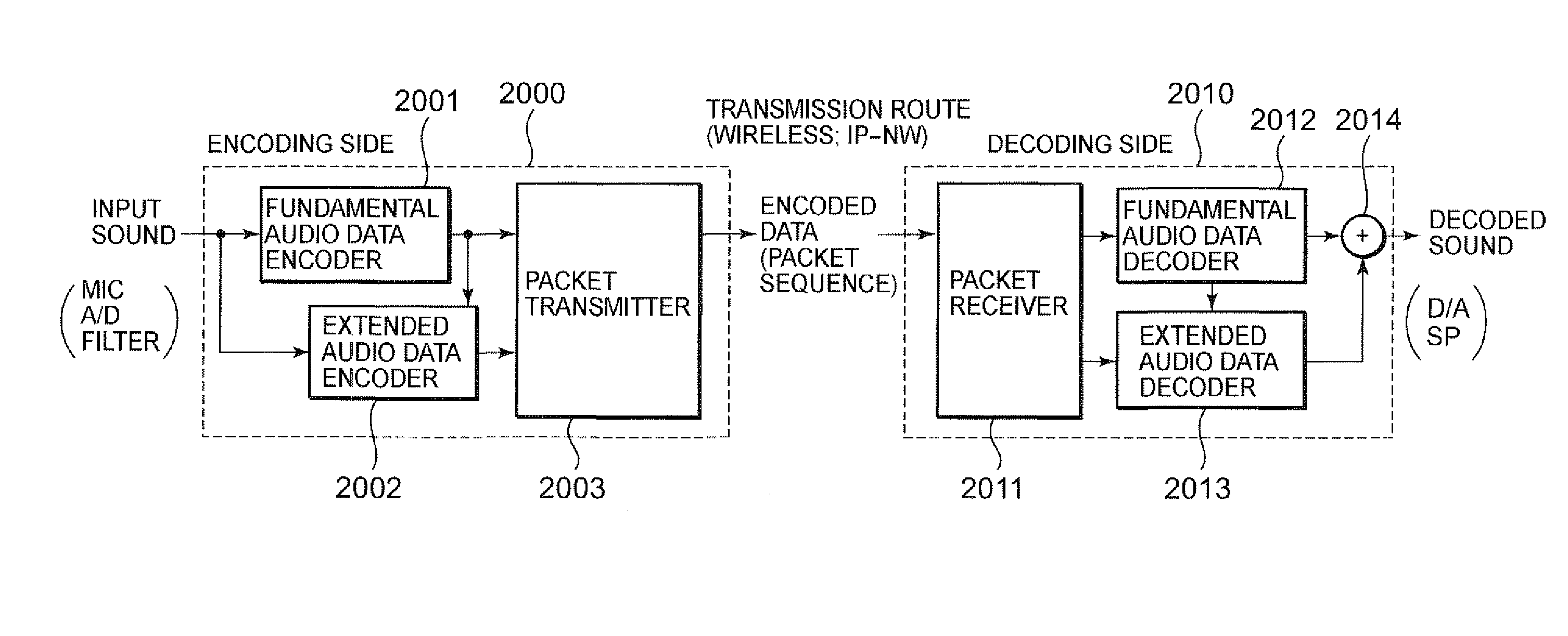
[0250]First, description will be given on a method to divide audio data by using scalable audio coding. Then, description will be given on a method to transmit the audio data by packets. In FIG. 30, a coding device 2000 at a transmitting side communication device encodes the input audio data (PCM data) from a microphone (MIC), an A / D converter, and a band division filter) by scalable audio coding method. By the scalable audio coding method, audio data is encoded at a fundamental audio data encoder 2001 and an extended audio data encoder 2002, and the fundamental audio data and the extended audio data are generated. The fundamental audio data encoder 2001 and the extended audio data encoder 2002 have different sampling frequencies used for coding. Low frequency components are encoded as fundamental audio data, and high frequency components are encoded as extended audio data. By inputting the coding data of the fundamental audio data to the extended audio data encoder 2002, an extende...


PUM


Abstract

A technique is disclosed, according to which it is possible to efficiently use network resources, to reduce the burden on a control device, and to control the communication between radio terminals by the control device when a transmitting side radio terminal and a receiving side radio terminal are connected to the same radio relay device. According to this technique, when a transmitting side UE1 and a receiving side UE2 are connected to the same E-Node B 103, the transmitting side UE1 divides a transmission packet addressed to UE2 into a first packet to be transmitted via a route not passing through ACGW 105 and a second packet to be transmitted via a route passing through ACGW 105, and the packets are transmitted to E-Node B 103. E-Node B 103 transmits the first packet to UE2 and also transmits the second packet to ACGW 105. ACGW 105 receives the second packet and transmits it to E-Node B 103. E-Node B 103 receives the second packet transmitted from ACGW 105 and transmits it to UE2. UE2 receives the first packet and the second packet and synthesizes them to restore the initial packet.

Description

TECHNICAL FIELD[0001]The present invention relates to a communication system using a packet network, a communication method, a radio terminal, a radio relay device, and a control device.BACKGROUND ART[0002]As described in the Non-Patent Documents 1 and 2 as given below, an architecture shown in FIG. 15 is proposed as a configuration of the next generation network of 3rd Generation Partnership Project (3GPP; registered trademark). In FIG. 15, user equipments (hereinafter referred as “UE” or “UEs”) UE 101 and UE 102 are connected to base stations E-Nodes B (Evolved Nodes B) 103 and 104 respectively via radio wave. Further, the base stations 103 and 104 are connected to access gateway (ACGW; or MME / UPE) 105, which is a control device on network side and connected via wired means. ACGW 105 performs user authentication processing by using a user authentication device 106, and it is judged whether UE 101 and UE 102 should be connected to the network or not. Also, by using a charging contr...

Claims


Application Information

Patent Timeline
IPC IPC(8): H04N7/32H04B7/14G10L19/00H04K1/00H04W12/02H04W28/02H04W76/00H04W88/02H04W92/14
CPCH04W76/022H04W88/04H04W80/04H04W76/12
Inventor MORIMOTO, TETSUROARAMAKI, TAKASHIEHARA, HIROYUKI
Owner PANASONIC INTELLECTUAL PROPERTY CORP OF AMERICA
Why Eureka
Try Eureka