Optical signal sampling apparatus and method and optical signal monitor apparatus and method using the same
- Summary
- Abstract
- Description
- Claims
- Application Information
AI Technical Summary
Benefits of technology
Problems solved by technology
Method used
Image


Examples
first embodiment
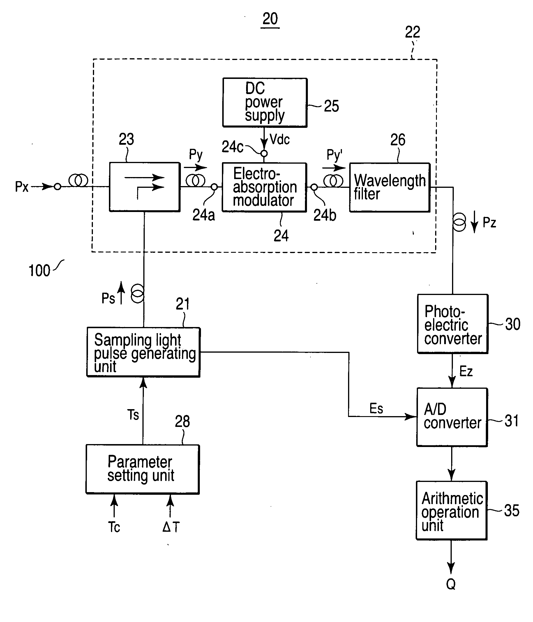
[0113]FIG. 1 is a block diagram shown for explaining the configuration of the optical signal sampling apparatus 100 and the optical signal monitor apparatus 20 using the same according to the first embodiment of the invention.
[0114]An optical signal sampling apparatus 100 according to the invention basically includes: a sampling light pulse generating unit 21 which generates a sampling light pulse Ps of a predetermined period to sample an optical signal to be sampled Px; and an optical sampling unit 22 which samples the optical signal to be sampled Px, with the sampling light pulse Ps from the sampling light pulse generating unit 21 and emits an optical pulse signal Pz obtained by the sampling, wherein the optical sampling unit 22 includes: an optical combiner 23 which combines the optical signal to be sampled Px and the sampling light pulse Ps from the sampling light pulse generating unit 21 with each other; an electroabsorption modulator 24 having two optical terminals 24a, 24b fo...
second embodiment
[0159]FIG. 6 is a block diagram shown for explaining the configuration of the optical signal sync sampling apparatus 100 and the optical signal monitor apparatus 20′ using the sampling apparatus 100 according to a second embodiment of the invention.
[0160]An example of the configuration of the optical signal monitor apparatus 20′ always capable of holding the synchronous state is shown in FIG. 6.
[0161]In the optical signal monitor apparatus 20′, the sampling light pulse generating unit 21, the optical sampling apparatus 22, the parameter setting unit 28, the photoelectric converter 30 and the A / D converter 31 are equivalent to the corresponding component parts of the first embodiment and therefore not described again.
[0162]In the optical signal monitor apparatus 20′, the output signal Ez of the photoelectric converter 30 is input to the fundamental wave component signal output unit 41.
[0163]The fundamental wave component signal output unit 41 is for outputting the fundamental wave co...
third embodiment
[0203]FIG. 12 is a block diagram shown for explaining the configuration of the optical signal sampling apparatus 100A and the optical signal monitor apparatus 20A using the apparatus 100A according to the third embodiment of the invention.
[0204]Specifically, in the optical sampling unit 22A making up the optical signal sampling apparatus 100A shown in FIG. 12, the optical signal Px to be monitored enters the polarized wave controller 23a, and the direction of polarization thereof is set orthogonal to the direction of polarization of the sampling light pulse Ps, after which the resulting light, together with the sampling light pulse Ps, is applied to and multiplexed in the optical coupler 23b of polarization multiplexing type making up the optical combiner23. The multiplexed light Py′ is applied to one optical terminal 24a of the electroabsorption modulator 24, and among the light rays emitted from the other optical terminal 24b, only the polarized component Pz of the optical signal ...
PUM
 Abstract
Description
Claims
Application Information
 - R&D
- Intellectual Property
- Life Sciences
- Materials
- Tech Scout
- Unparalleled Data Quality
- Higher Quality Content
- 60% Fewer Hallucinations
Browse by: Latest US Patents, China's latest patents, Technical Efficacy Thesaurus, Application Domain, Technology Topic, Popular Technical Reports.
© 2025 PatSnap. All rights reserved.Legal|Privacy policy|Modern Slavery Act Transparency Statement|Sitemap|About US| Contact US: help@patsnap.com