Power Tool

Inactive Publication Date: 2010-09-23
HITACHI KOKI CO LTD
View PDF8 Cites 3 Cited by
  • Summary
  • Abstract
  • Description
  • Claims
  • Application Information

AI Technical Summary

Benefits of technology

[0016]With this arrangement, the length of the power tool in the direction f

Problems solved by technology

Hence, even if driving force is transmitted in a staged manner with the intermediate clutch, a collision with a large speed difference occurs at some s

Method used


Image

  • Power Tool
  • Power Tool
  • Power Tool

Examples


first embodiment

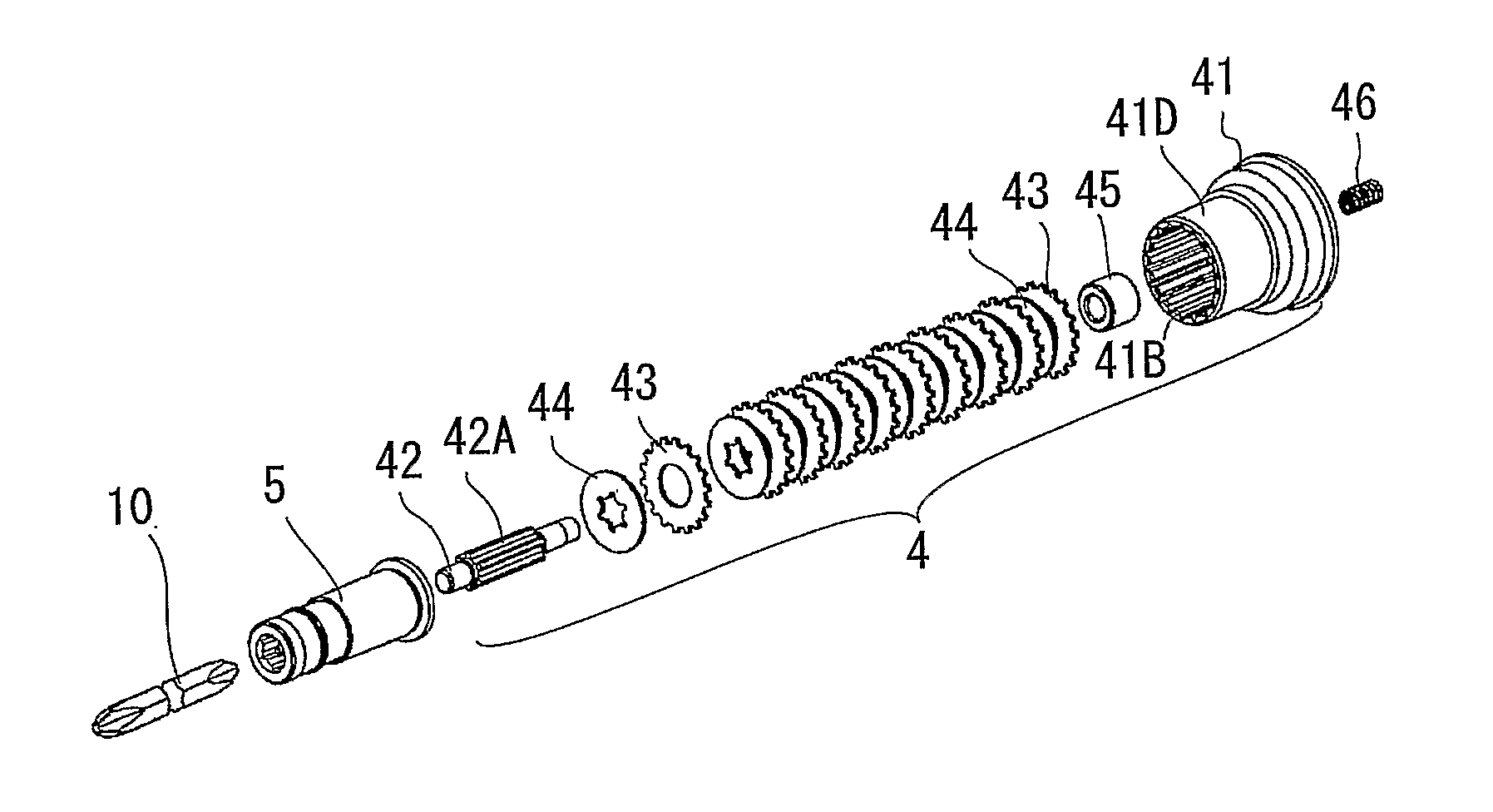
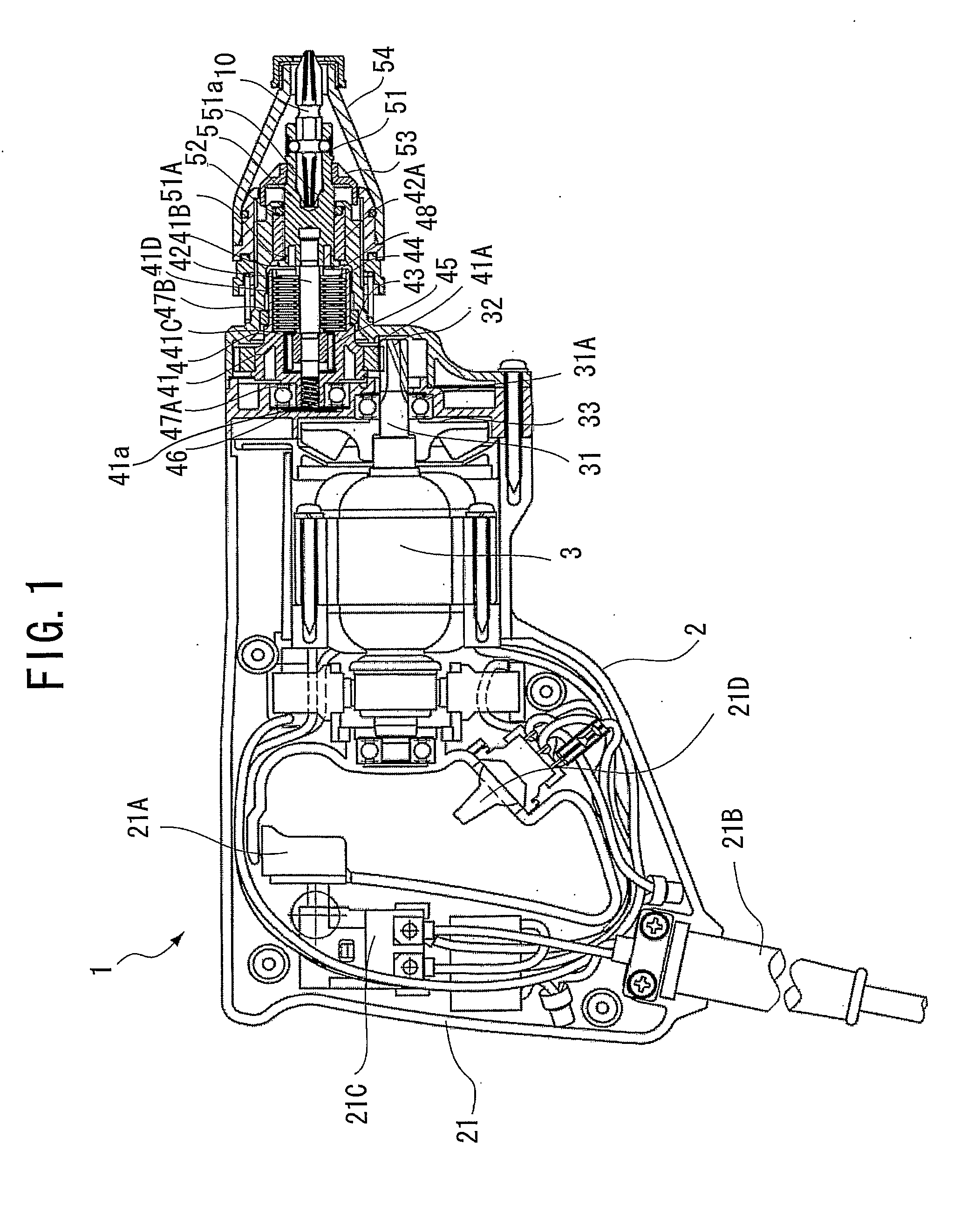
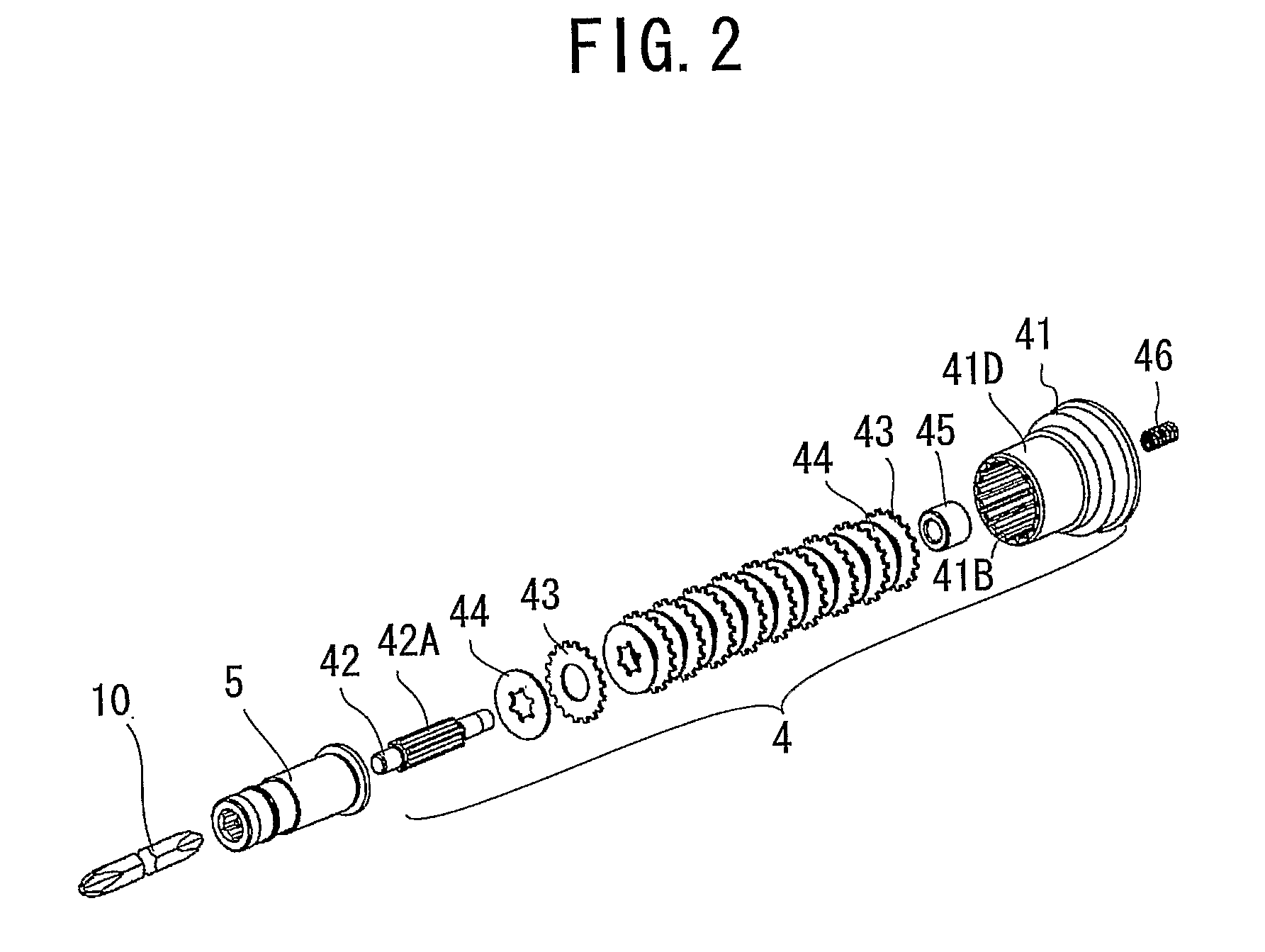
[0066]A power tool according to a first embodiment of the present invention will be described while referring to FIGS. 1 through 6. The power tool of the present embodiment is applied to a screw driver. As shown in FIG. 1, a screw driver 1 mainly includes a housing 2, a motor 3, a clutch section 4, and an end-bit mounting section 5. A bit 10 serving as an end bit is mounted on the end-bit mounting section 5. The side on which the bit 10 is mounted is defined as the front side of the screw driver 1, and the side of a handle 21 to be described later is defined as the rear side of the screw driver 1.

[0067]The housing 2 constitutes an outer shell of the screw driver 1, and includes the handle 21 serving as a handle section at its rear end. The handle 21 is provided with a trigger 21A for performing drive control of the motor 3 and a switch 21D for performing control of the rotation direction (forward and reverse) of the motor 3. The handle 21 is also provided with a power code 21B that ...

second embodiment

[0085]A power tool according to a second embodiment of the present invention will be described while referring to FIG. 7. The power tool of the present embodiment is applied to a screw driver. A screw driver 101 shown in FIG. 7 has basic structure which is the same as the structure of the screw driver 1 according to the first embodiment.

[0086]A rotational shaft 131 of a motor (not shown) is supported by a housing 102 via a bearing 131A, and has a pinion 132 at its distal end (front end). A fan 133 is fixed to the proximal end (rear end) of the rotational shaft 131. A clutch section 104 mainly includes a clutch drum 141, a spline shaft 142, first clutch plates 143 serving as drive members, second clutch plates 144 serving as follow members, and a one-way clutch 145. A gear 141A is provided at the outer circumference of a portion of the clutch drum 141 so as to meshingly engage the pinion 132. The clutch drum 141 includes an accommodating section 141E formed with a space that accommod...


PUM


Abstract

A friction clutch includes drive and follow members. The drive member rotates together with the driving section and has a drive-side contact surface. The follow member rotates together with the end-bit mounting section and has a follow-side contact surface contactable with the drive-side contact surface. The friction clutch is movable between a transmission position where frictional force is produced between the drive-side and follow-side contact surfaces so that the output shaft and end-bit mounting section (5) can rotate together, and a cutoff position where the output shaft and end-bit mounting section are non-rotatable together. A shaft (42) has one end side rotatably supported by a first bearing (31A) and another end side rotatably supported by a second bearing (47A). The shaft supports the drive and follow members so that the drive and follow members are arranged coaxially in the axial direction. The drive and follow members are arranged between the first and second bearings.

Description

TECHNICAL FIELD[0001]The present invention relates to a power tool.BACKGROUND ART[0002]Conventionally, a plate material such as a plaster board is fixed to a ceiling or to a wall by screw driving. A screw driver is a power tool for performing this screw driving. Japanese Examined Patent Application Publication No. H3-5952 discloses a screw driver including a motor and an end bit driven by the motor for driving a screw. The screw driver further includes a first clutch element, an intermediate clutch, and a second clutch element in this order between the motor and the end bit. With the screw driver, cam threads on the first clutch element located at the motor side engage motor-side cam threads on the intermediate clutch to rotate the intermediate clutch, and an engagement member of the intermediate clutch further rotates the second clutch element.DISCLOSURE OF THE INVENTION[0003]However, the clutches in the conventional screw driver engage each other in a full speed condition of the m...

Claims


Application Information

Patent Timeline
IPC IPC(8): F16D11/04
CPCB25B23/141B25B23/0064
Inventor SATO, SHINICHIRO
Owner HITACHI KOKI CO LTD
Why Eureka
Try Eureka