
Charged particle beam writing method, method for detecting position of reference mark for charged particle beam writing, and charged particle beam writing apparatus

Active Publication Date: 2010-09-23
NUFLARE TECH INC
View PDF7 Cites 11 Cited by
  • Summary
  • Abstract
  • Description
  • Claims
  • Application Information

AI Technical Summary

Benefits of technology

[0009]Objects of the present invention are to provide a charged particle beam writing method, a method for detecting the position of a reference mark for charged particle beam writing, and a charged particle beam writing apparatus, which are capable of reproducibly detecting the position of a reference mark without an influence of an edge roughness of the stepped reference mark that is formed on a sample.

Problems solved by technology

However, a mask material through which the EUV light can be transmitted without attenuation has not been found.
In a process for forming the reflective mask, if an environmental contaminant is mixed into the multilayer film or the multilayer film is formed on an irregularity located on the surface of the substrate, then the ordered structure of the multilayer film may be disordered, resulting in the multilayer film having a phase defect.
When light (such as the EUV light) having a short wavelength is used as exposure light, a phase defect may occur and affect exposure irrespective of an extremely small irregularity.

Method used


Image

  • Charged particle beam writing method, method for detecting position of reference mark for charged particle beam writing, and charged particle beam writing apparatus
  • Charged particle beam writing method, method for detecting position of reference mark for charged particle beam writing, and charged particle beam writing apparatus
  • Charged particle beam writing method, method for detecting position of reference mark for charged particle beam writing, and charged particle beam writing apparatus

Examples


Embodiment Construction

[0023]An embodiment of the present invention is described below in detail.

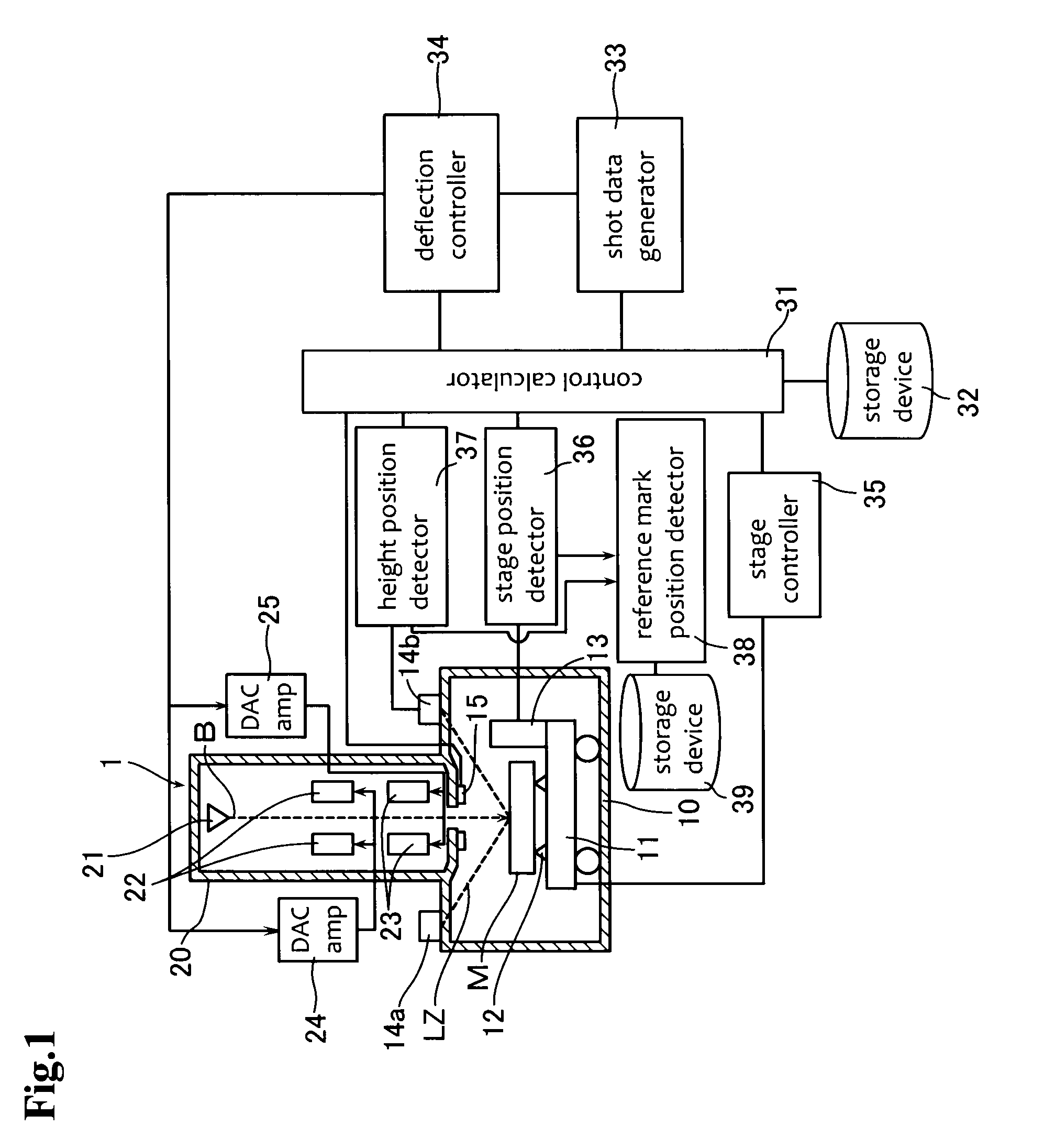
[0024]FIG. 1 is a schematic view showing the configuration of an electron beam writing apparatus according to the embodiment of the present invention. The electron beam writing apparatus has a writing apparatus body 1. The writing apparatus body 1 has a writing chamber (also called a sample chamber) 10 and a lens barrel of electron optical system 20. The lens barrel of electron optical system 20 is provided above the writing chamber 10.

[0025]A stage 11 is located in the writing chamber 10. The stage 11 is capable of moving in X and Y directions with a mask M or sample placed thereon. The stage 11 has a holding member 12 on its front surface. The holding member 12 holds a back surface of the mask M.

[0026]A reflective mirror 13 is located near an edge portion of the stage 11. The reflective mirror 13 is used to measure the position of the stage 11. A stage controller 35 controls the stage 11 to cause the stage 1...


PUM


Abstract

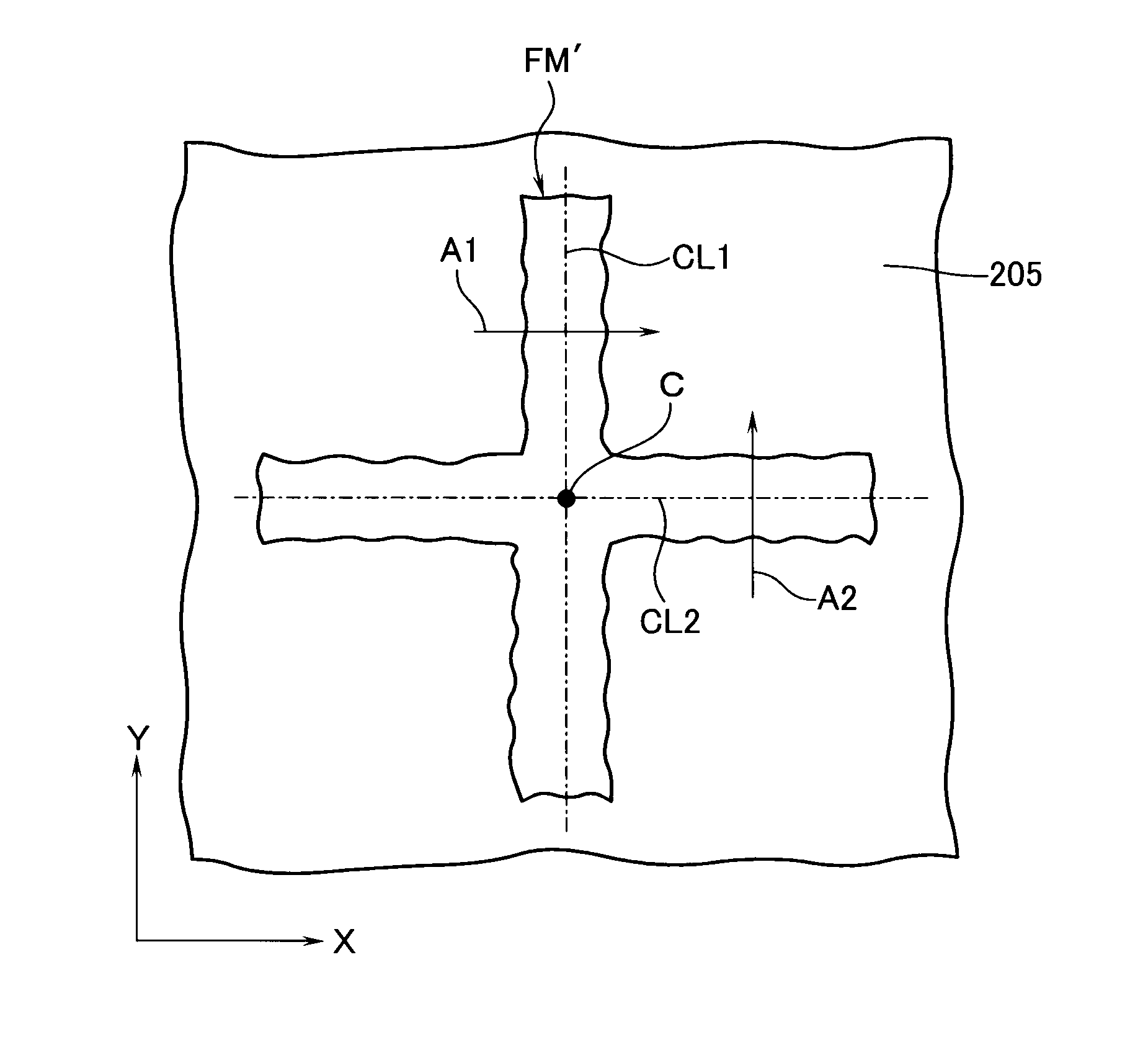
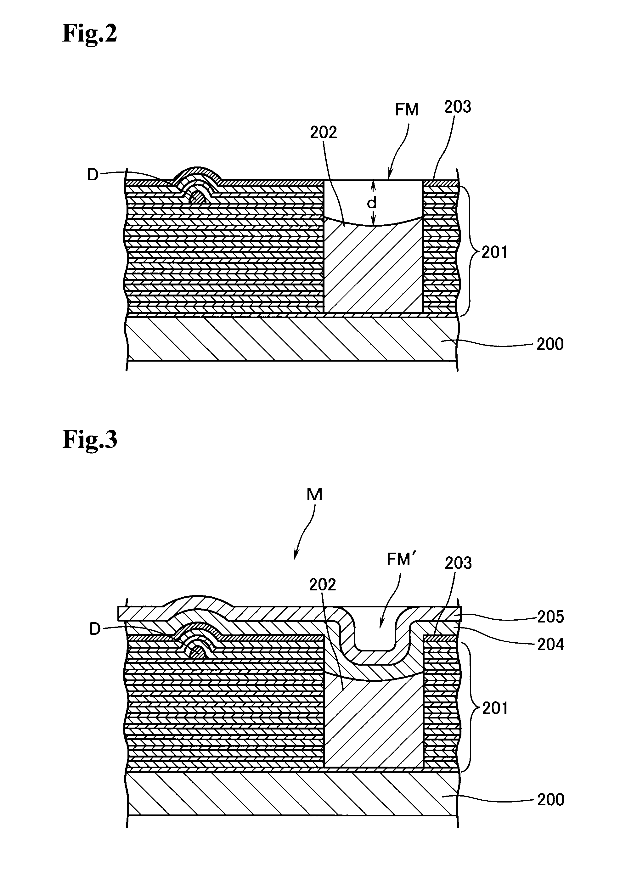
The reference mark has steps and is formed on a sample. A stage moves in X and Y directions. The sample M is placed on the stage. An optical lever type height position sensor emits light to detect the reference mark FM′ by the stage being scanned. The spot position of light reflected on the sample is detected in position sensitive detector. The X and Y coordinates of the position of the stage positioned when the spot position of the reflected light is changed is detected. The detected X and Y coordinates are regarded as the position C of the reference mark FM′. The position of a phase defect D located in the sample M is specified on the basis of the position C of the reference mark FM′. The position of a portion on which writing is to be performed is determined on the basis of a relationship with the specified position of the phase defect D.

Description

BACKGROUND OF THE INVENTION[0001]1. Field of the Invention[0002]The present invention relates to a charged particle beam writing method, a method for detecting the position of a reference mark for charged particle beam writing, and a charged particle beam writing apparatus.[0003]2. Background Art[0004]Semiconductor devices are being further shrunk in size. Along with such a trend, extreme ultraviolet (EUV) lithography has attracted attention in recent years. In the extreme ultraviolet lithography, extreme ultraviolet light is used as exposure light. Since the wavelength of the EUV light is as short as 13.5 nanometers, it is expected that a resolution in use will be enhanced. However, a mask material through which the EUV light can be transmitted without attenuation has not been found. Thus, not a transmissive mask but a reflective mask is typically used to perform the EUV lithography (refer to Japanese Patent Laid-open No. 2004-289110). The reflective mask has a multilayer film and ...

Claims


Application Information

Patent Timeline
IPC IPC(8): H01J37/30H01J37/20G01B11/14G03F1/76G03F1/78G03F7/20H01L21/027
CPCB82Y10/00B82Y40/00H01J37/3174H01J2237/30455H01J2237/2482H01J2237/30438H01J2237/20
Inventor YOSHITAKE, SHUSUKE
Owner NUFLARE TECH INC
Learn More