

LED module, LED illumination means, and LED lamp for the energy-efficient reproduction of white light
a technology of led modules and led lamps, applied in the field of lighting, can solve the problems of increased control or regulation expenditure, low color rendition of rgb solutions, and temperature dependence of emission colors, and achieve the effect of high color rendition and highest efficiency
- Summary
- Abstract
- Description
- Claims
- Application Information
AI Technical Summary
Benefits of technology
Problems solved by technology
Method used
Image

Examples
Embodiment Construction
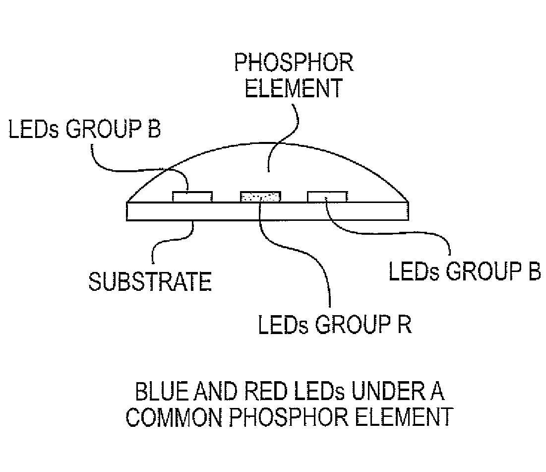
[0022]A purpose of the present invention is to provide an LED module for LED lighting means and LED lamps which has the highest possible efficiency and high color rendition and does not thereby exhibit the disadvantages of existing solutions. The LED module according to embodiments of the invention combines the advantages of the phosphor-based LED solutions with the advantages of the RGB solutions.
BRIEF DESCRIPTION OF THE DRAWING
[0023]The invention is further described below by means of the subsequent detailed description of advantageous embodiment examples of the invention, reference being made to accompanying drawing, wherein:
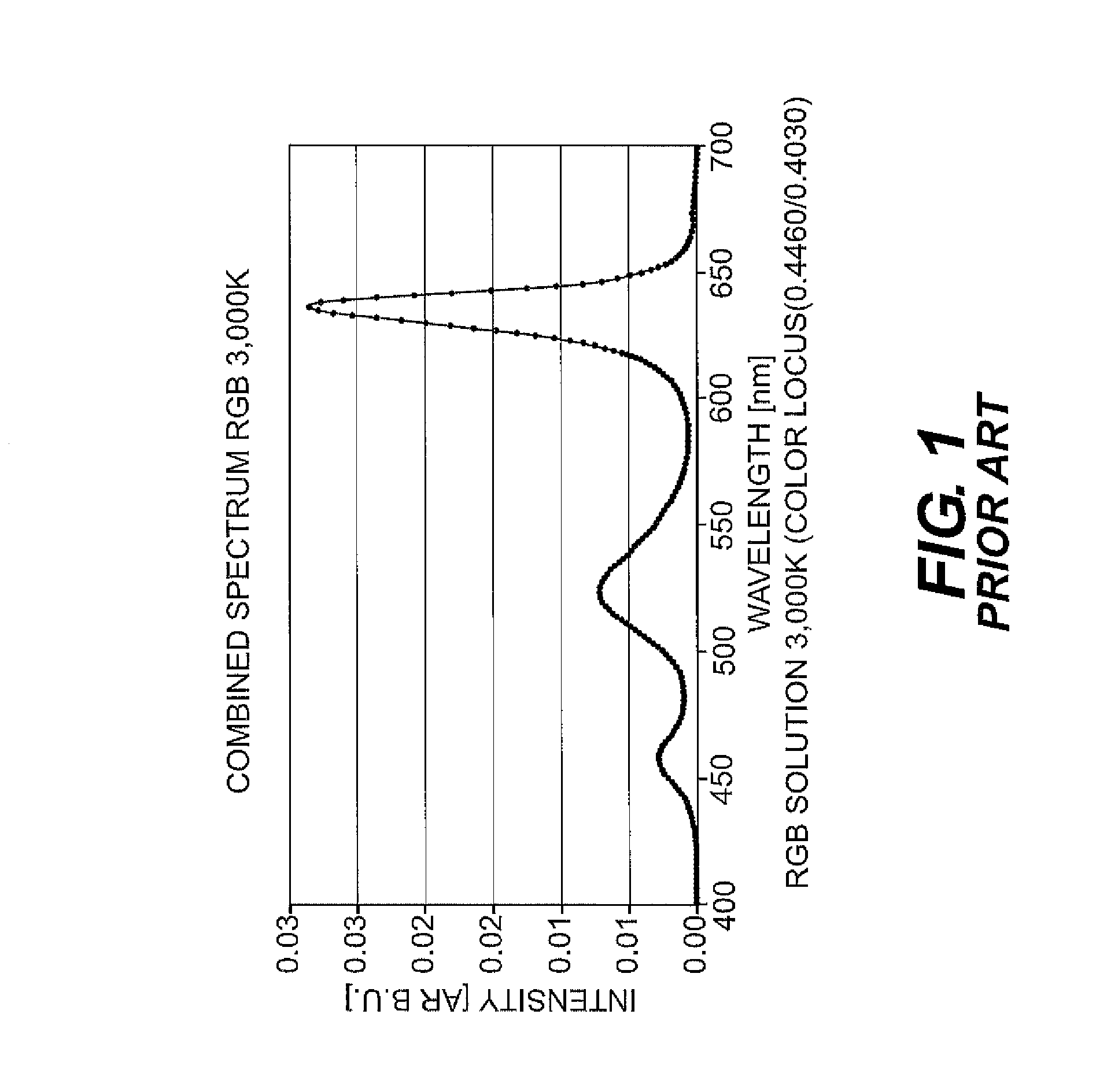
[0024]FIG. 1 is a graph of a spectrum RGB solution 3000K according to the prior art;
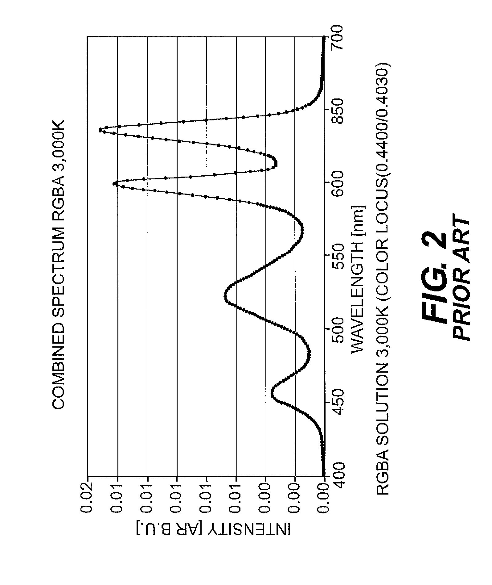
[0025]FIG. 2 is a graph of a spectrum RGBA solution 3000K according to the prior art;
[0026]FIG. 3 is a graph of a spectrum phosphor solution 3000K and V(lambda) of the prior art;
[0027]FIG. 4 is a graph of a comparison of the cumulative radiant power to the cumulative luminous ...
PUM
 Abstract
Description
Claims
Application Information