
Carrier tape feeder for chip mounter

a mounter and carrier tape technology, applied in packaging bottles, packaging goods types, transportation and packaging, etc., can solve the problems of difficult to accurately feed components, many problems in the work of mounting components, and tangled vinyl covers around the discharge unit of vinyl covers, so as to prevent problems and facilitate discharge

Inactive Publication Date: 2010-09-23
KIM KWANG SIK
View PDF7 Cites 61 Cited by
  • Summary
  • Abstract
  • Description
  • Claims
  • Application Information

AI Technical Summary

Benefits of technology

[0010]Therefore, it is an object of the present invention to provide a carrier tape feeder for a chip mounter, which basically prevents the problems caused when a discharged vinyl cover gets tangled or comes into contact together after the vinyl cover is separated from a base tape of a carrier tape and components retained in the carrier tape are picked up, so that the vinyl cover is smoothly discharged.
[0011]It is another object of the present invention to provide a carrier tape feeder for a chip mounter, which normally consecutively and automatically feeds electronic components retained in receiving spaces of a carrier tape even though the carrier tape is transferred in an abnormally deformed state not in a straight flat state, and which easily separates a vinyl cover affixed to a base tape at a front end of the carrier tape.
[0015]Preferably, the tape guide may comprise: a blade to separate the vinyl cover from the base tape of the supplied carrier tape; a hook with a front end bent in a ‘┐’ shape to catch a front end of the carrier tape and thus to easily separate the vinyl cover from the base tape; a leaf spring to be installed to be positioned under the blade and the front end of the hook and to support the carrier tape; and a vinyl cover guider to guide the vinyl cover separated by the blade.

Problems solved by technology

Therefore, the vinyl cover gets tangled around a vinyl cover discharge unit.
This changes the pitch of the carrier tape, thereby making it difficult to accurately feed the components.
In this case, when the vinyl cover discharged by being separated from the carrier tape in each tape feeder gets tangled together, static electricity is generated to cause many problems in the work for mounting components.
Consequently, there are caused serious problems of stopping the work to mount the components or producing defective products.
However, when a thickness of an electronic component retained in the carrier tape is thick or when the base tape is transferred in a uneven and bent state, along the length direction even though the thickness of the electronic component is not thick, the electronic components retained in the carrier tape cannot be consecutively and automatically fed to the chip mounter.
Moreover, since the vinyl cover is affixed to the base tape, even though the carrier tape is fed in the normal state, it is difficult to separate the vinyl cover from the base tape at a front end of the carrier tape.

Method used


Image

  • Carrier tape feeder for chip mounter
  • Carrier tape feeder for chip mounter
  • Carrier tape feeder for chip mounter

Examples


first embodiment

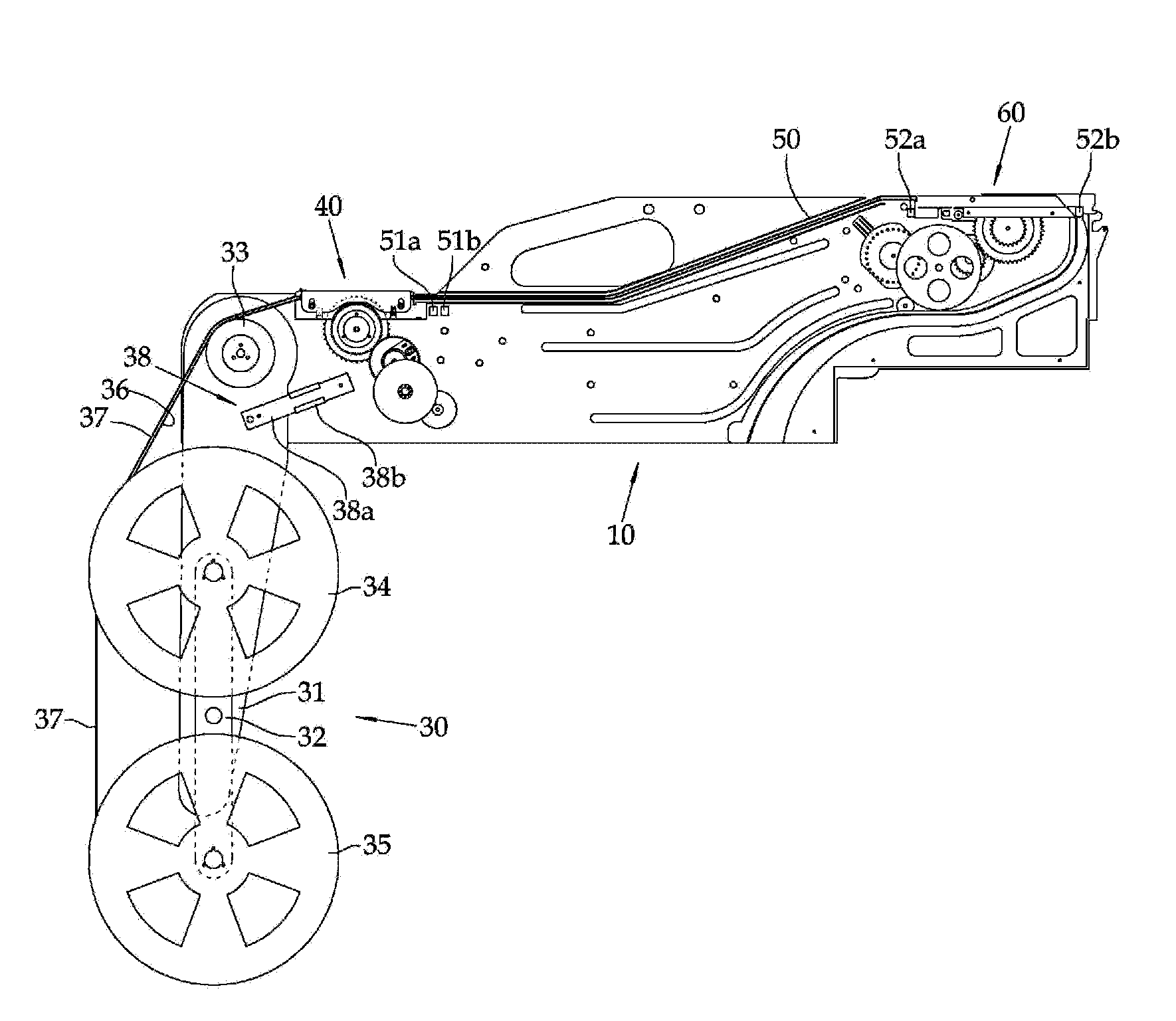
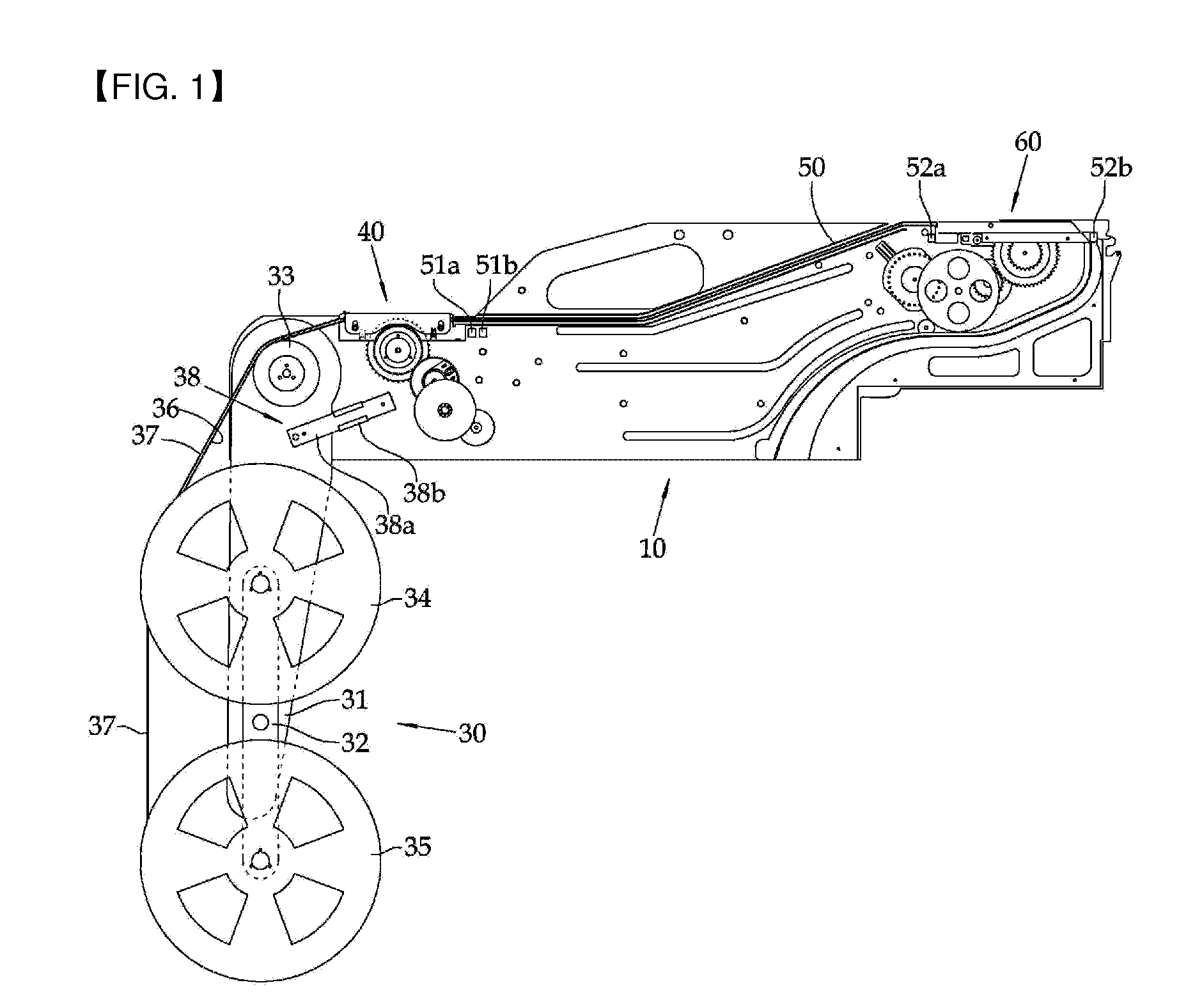
[0043]As illustrated in FIG. 5, the pickup section 60 according to the present invention is installed in the other end of the tape feeder body 10, i.e., at the front of the tape feeder body 10. The pickup section 60 comprises: a tape guide 61 and a second driving member. The tape guide 61 separates the base tape 21 and the vinyl cover 23 of the carrier tape supplied from the tape guide section 50 so that the components retained in the receiving spaces 22 of the base tape 21 can be picked up, and then guides the base tape 21 and the vinyl cover 23 in the same direction simultaneously so that the base tape 21 and the vinyl cover 23 are discharged. The second driving member generates a driving force to transfer the carrier tape. The pickup section 60 further comprises: a tape discharge guide unit 68. After the components retained in the receiving spaces 22 of the base tape 21 are picked up by a nozzle of the chip mounter, the tape discharge guide unit 68 guides the base tape 21 and the...

second embodiment

[0054]FIG. 13 illustrates a pickup section according to a A tape guide 61 comprises: a blade 62, a hook 621, a vinyl cover guider 64, and a leaf spring 622. The blade 62 separates a vinyl cover from a base tape of a carrier tape being supplied. The hook 621 is positioned in front of the blade 62. A front end of the hook 621 is bent in a ‘┐’ shape. As the carrier tape is caught by the front end of the hook 621, the vinyl cover is easily separated from the base tape at a front end of the carrier tape. The vinyl cover guider 64 guides the vinyl cover separated by the blade 62. The leaf spring 622 is installed to be positioned under the blade 62 and the front end of the hook 621. The leaf spring 622 supports the carrier tape to be in contact with a level plate 69 which is attached to a bottom surface of the tape guide 61.

[0055]The hook 621 is positioned in front of the blade 62 (i.e., the hook 621 is positioned to be close to a tape guide section rather than the blade). The front end o...


PUM

PropertyMeasurementUnit
Forceaaaaaaaaaa
Shapeaaaaaaaaaa
Stiffnessaaaaaaaaaa

Abstract

There is provided a carrier tape feeder for a chip mounter, which consecutively and automatically supplies a carrier tape which retains small electronic components at regular intervals and is sealed by a vinyl cover to the chip mounter to mount the components onto a printed circuit board.To consecutively and automatically supply components retained in a carrier tape to a chip mounter, the carrier tape feeder for the chip mounter comprises: a pickup section to separate a part of a vinyl cover from a base tape of the carrier tape so that the components retained in the base tape can be picked up, wherein the pickup section connected to an end of a tape feeder body comprises: a tape guide to secure a path of the carrier tape from which the part of the vinyl cover is separated longitudinally and to discharge the base tape and the vinyl cover together in the same direction simultaneously, wherein the tape guide comprises: a blade to separate longitudinally the vinyl cover from the base tape of the carrier tape being fed; and a vinyl cover guider to guide the separated vinyl cover.

Description

CROSS-REFERENCE TO RELATED APPLICATION[0001]This application claims the benefit of Korean Patent Application Nos. 10-2009-0019757 filed on Mar. 9, 2009 and 10-2010-0010848 filed on Feb. 5, 2010, the disclosure of which is hereby incorporated herein by reference in its entirety.BACKGROUND OF THE INVENTION[0002]1. Field of the Invention[0003]The present invention relates to a carrier tape feeder for a chip mounter, and more particularly, to a carrier tape feeder for a chip mounter, which consecutively and automatically feeds a carrier tape which retains small electronic components, such as semiconductor chips, at regular intervals and seals the components with a vinyl cover, onto a chip mounter for mounting the components onto a printed circuit board.[0004]2. Description of the Related Art[0005]A chip mounter is an apparatus to pick up small components fed by a feeder by vacuum suction using a nozzle of a head, and to mount, at high-speed and with high-precision, the components onto a...

Claims


Application Information

Patent Timeline
IPC IPC(8): H05K13/02
CPCB65H37/002H05K13/0417B65H2701/1942B65H45/08H05K13/0419
Inventor KIM, KWANG-SIK
Owner KIM KWANG SIK
Learn More