
Vehicle, electrical charging apparatus, and control method

a charging apparatus and electrical charging technology, applied in hybrid vehicles, process and machine control, instruments, etc., can solve the problems of infrastructure destruction and drag of charging cables, and achieve the effect of preventing the destruction of electrical charging infrastructur

Inactive Publication Date: 2010-09-23
TOYOTA JIDOSHA KK
View PDF0 Cites 46 Cited by
  • Summary
  • Abstract
  • Description
  • Claims
  • Application Information

AI Technical Summary

Benefits of technology

[0011]This invention provides a vehicle, an electrical charging apparatus and a control method which are capable of preventing destruction of an electrical charging infrastructure even if a vehicle moves while being charged.
[0013]In the vehicle constructed in this manner, if the amount of movement of the vehicle is greater than or equal to the predetermined amount, the engagement of the vehicle with the electrical charging apparatus is released. As a result, if the vehicle moves while being charged, the engagement between the vehicle and the electrical charging apparatus is released, so that the destruction of the electrical charging apparatus due to movement of the vehicle can be prevented.
[0014]Besides, the electrical charging portion may ejects the electrical charging apparatus after releasing the engagement with the electrical charging apparatus, if the determination portion determines that the amount of movement of the vehicle is greater than or equal to the predetermined amount. In this case, since the electrical charging apparatus is ejected, if the vehicle moves while being charged, so that the destruction of the electrical charging apparatus due to movement of the vehicle can be prevented.
[0017]In the electrical charging apparatus constructed in this manner, the engagement of the electrical charging apparatus with the vehicle is released if the amount of movement of the vehicle is greater than or equal to the predetermined amount. As a result, if the vehicle moves while being charged, the engagement between the vehicle and the electrical charging apparatus is released, so that the destruction of the electrical charging apparatus due to movement of the vehicle can be prevented.
[0019]Besides, the electrical charging apparatus may further include an electrical charging control portion that stops charging of the vehicle if the amount of movement of the vehicle is greater than or equal to the predetermined amount. In this case, when the amount of movement of the vehicle is greater than or equal to the predetermined amount and therefore the engagement between the engagement portion and the vehicle is released, the electrical charging apparatus stops charging the vehicle, so that waste of electric power can be prevented.
[0021]Since the charging is controlled in this manner, the engagement of the vehicle with the electrical charging apparatus is released if the amount of movement of the vehicle is greater than or equal to the predetermined amount. As a result, if the vehicle moves while being charged, the engagement between the vehicle and the electrical charging apparatus is released, so that the destruction of the electrical charging apparatus due to movement of the vehicle can be prevented.

Problems solved by technology

However, in these related-art technologies, there is a problem that when a vehicle moves while being charged, the charging cable will be dragged and an infrastructure will be destroyed.

Method used


Image

  • Vehicle, electrical charging apparatus, and control method
  • Vehicle, electrical charging apparatus, and control method
  • Vehicle, electrical charging apparatus, and control method

Examples


embodiment 1

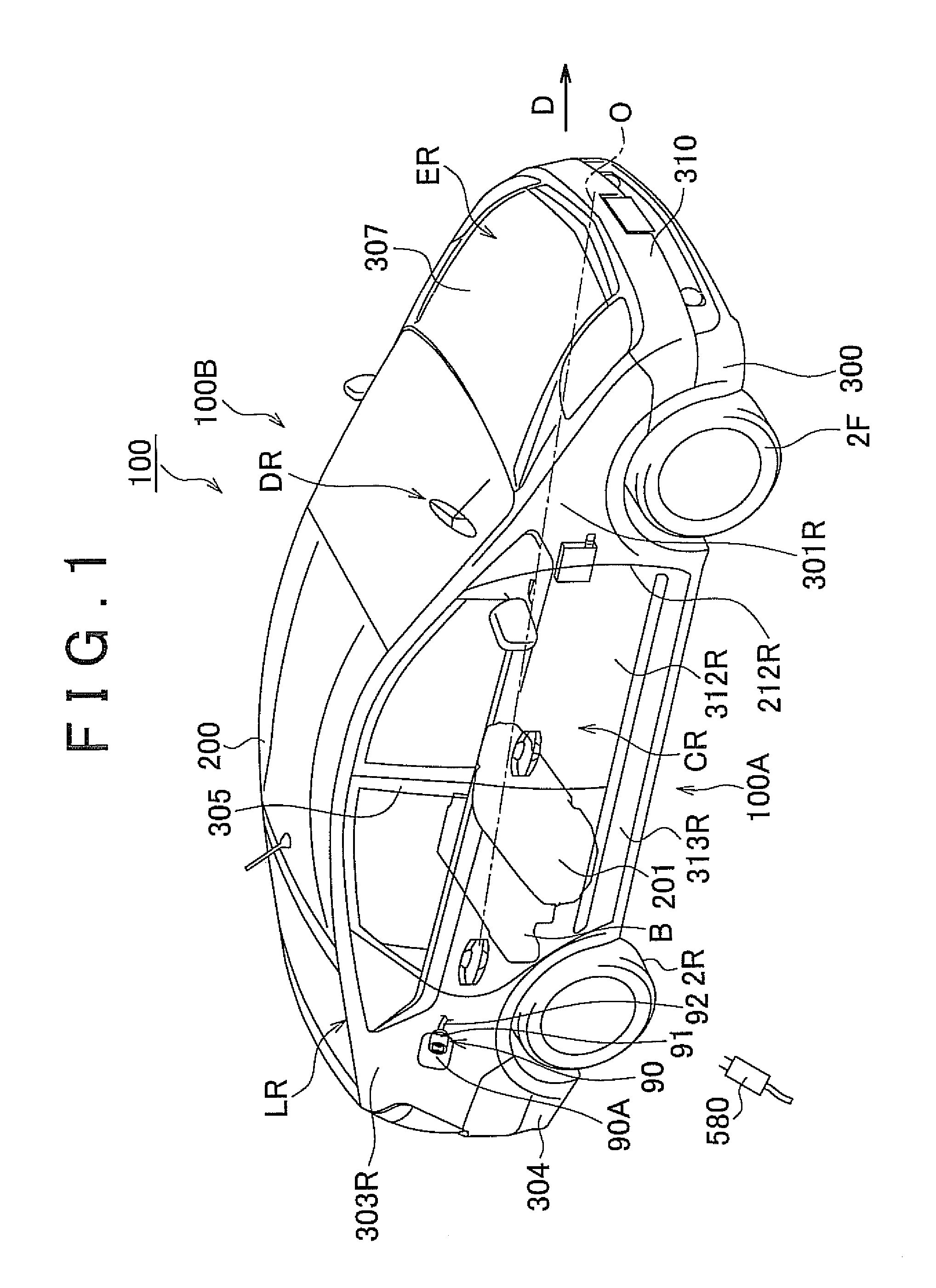
[0036]FIG. 1 is a schematic diagram of a vehicle that is charged by an electrical charging apparatus in accordance with Embodiment 1 of the invention. Referring to FIG. 1, a hybrid vehicle 100 includes a vehicle main body 200 formed of a body and exterior parts, a pair of front wheels (tire wheels) 2F provided on a front-side portion of the hybrid vehicle 100 in the traveling direction D, and a pair of rear wheels (tire wheels) 2R provided on a rear-side portion of the vehicle in the traveling direction D.

[0037]The vehicle main body 200 includes an engine compartment ER that is provided in a front-side portion of the hybrid vehicle 100 in the traveling direction D, an occupant compartment CR adjacent to a rearward side of the engine compartment ER in the traveling direction D, and a trunk compartment LF adjacent to a rearward side of the occupant compartment CR in the traveling direction D.

[0038]The body of the vehicle main body 200 adopted herein is, for example, a monocoque body. ...

embodiment 2

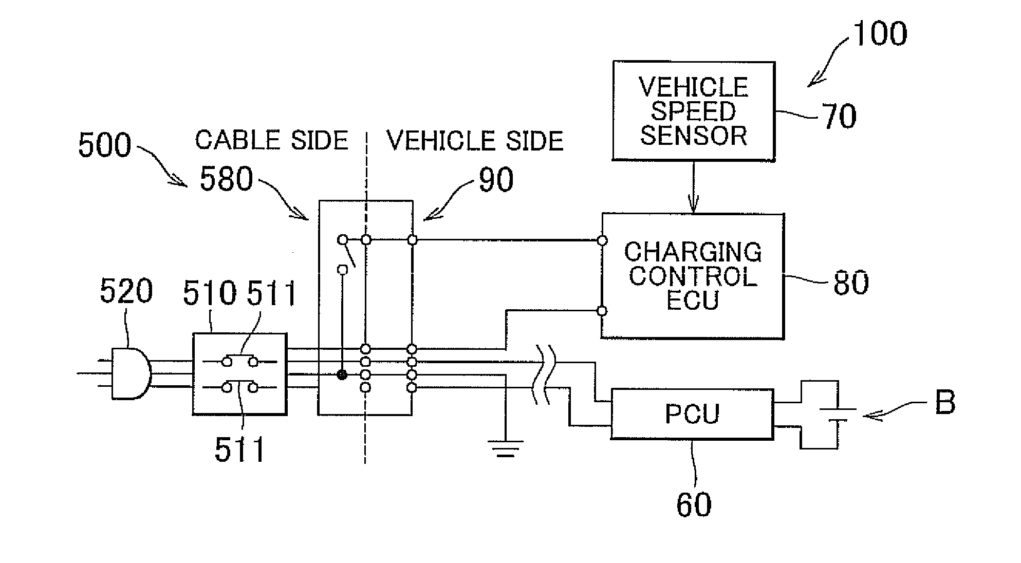
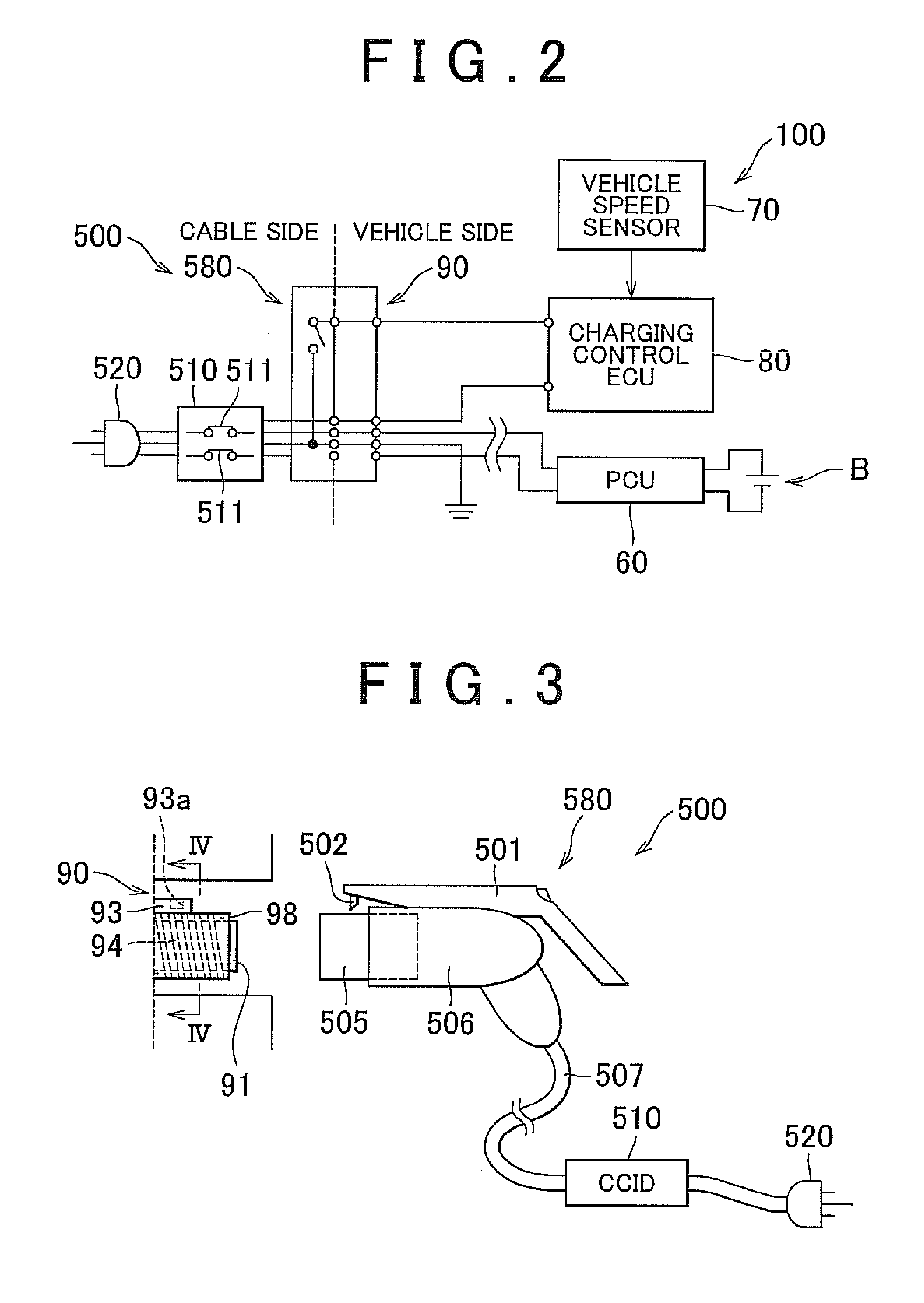
[0084]The electrical charging apparatus 500 in accordance with Embodiment 2 is an electrical charging apparatus 500 that engages with a portion of the hybrid vehicle 100 to electrically charge the hybrid vehicle 100, and includes the pressure sensor 519 as a detection portion that detects motion of the hybrid vehicle 100, and the charging-purpose plug 580 as an engagement portion that engages with the hybrid vehicle 100 if the amount of movement of the hybrid vehicle 100 commensurate with the information detected by the pressure sensor 519 is less than a predetermined amount, and that releases the engagement with the hybrid vehicle 100 if the amount of movement of the hybrid vehicle 100 is greater than or equal to the predetermined amount.

[0085]The electrical charging apparatus 500 further includes the charging cable box 510 as an electrical charging control portion that stops charging the hybrid vehicle 100 if the amount of movement of the hybrid vehicle 100 is greater than or equa...


PUM


Abstract

An electrical charging apparatus includes: an electrical charging control ECU that makes a determination about motion of a hybrid vehicle; and a charging-purpose plug which engages with the hybrid vehicle if the amount of movement of the vehicle is less than a predetermined value, and which releases the engagement with the hybrid vehicle if the amount of movement of the vehicle is greater than or equal to the predetermined value. According to the invention, even if the vehicle moves while being charged, the dragging of the charging cable is prevented.

Description

INCORPORATION BY REFERENCE[0001]The disclosure of Japanese Patent Application No. 2009-070053 filed on Mar. 23, 2009 including the specification, drawings and abstract is incorporated herein by reference in its entirety.BACKGROUND OF THE INVENTION[0002]1. Field of the Invention[0003]The invention relates to a vehicle, an electrical charging apparatus, and a control method. More specifically, the invention relates to a vehicle that has an electricity storage apparatus, an electrical charging apparatus that electrically charges the vehicle, and a control method for electrically charging a vehicle.[0004]2. Description of the Related Art[0005]Vehicles and electrical charging apparatuses as mentioned above are disclosed in, for example, Japanese Patent Application Publication No. 5-328532 (JP-A-5-328532), Japanese Patent Application Publication No. 5-328619 (JP-A-5-328619), Japanese Patent Application Publication No. 6-153319 (JP-A-6-153319), and Japanese Patent Application Publication N...

Claims


Application Information

Patent Timeline
Patent Type & Authority Applications(United States)
IPC IPC(8): G06F7/00H02J7/00
CPCB60L11/1818B60L2230/12B60W2520/10Y02T90/14Y02T10/7088Y02T90/121Y02T10/7005B60L53/16B60L53/18Y02T10/70Y02T10/7072Y02T90/12
Inventor ITO, TAKAHIROINOUE, YUKI
Owner TOYOTA JIDOSHA KK
Learn More