Eureka AIR delivers breakthrough ideas for toughest innovation challenges, trusted by R&D personnel around the world.

System and method for operating a dual clutch transmission during failure of an engine speed sensor or a bus connection between control modules

Active Publication Date: 2010-09-23
GETRAG GETRIEBE & ZAHNRADFABRIK HERMANN HAGENMEYER GMBH & CO KG +2
View PDF2 Cites 16 Cited by
  • Summary
  • Abstract
  • Description
  • Claims
  • Application Information

AI Technical Summary

Benefits of technology

[0008]Therefore, it is an object of the present invention to provide a system and method for ensuring the continuing operation of an automated transmission during a failure of a data bus connection between control modules being responsible for different components of the drive line of a motor vehicle, which in turn are to be adapted to each other during a gear shift.

Problems solved by technology

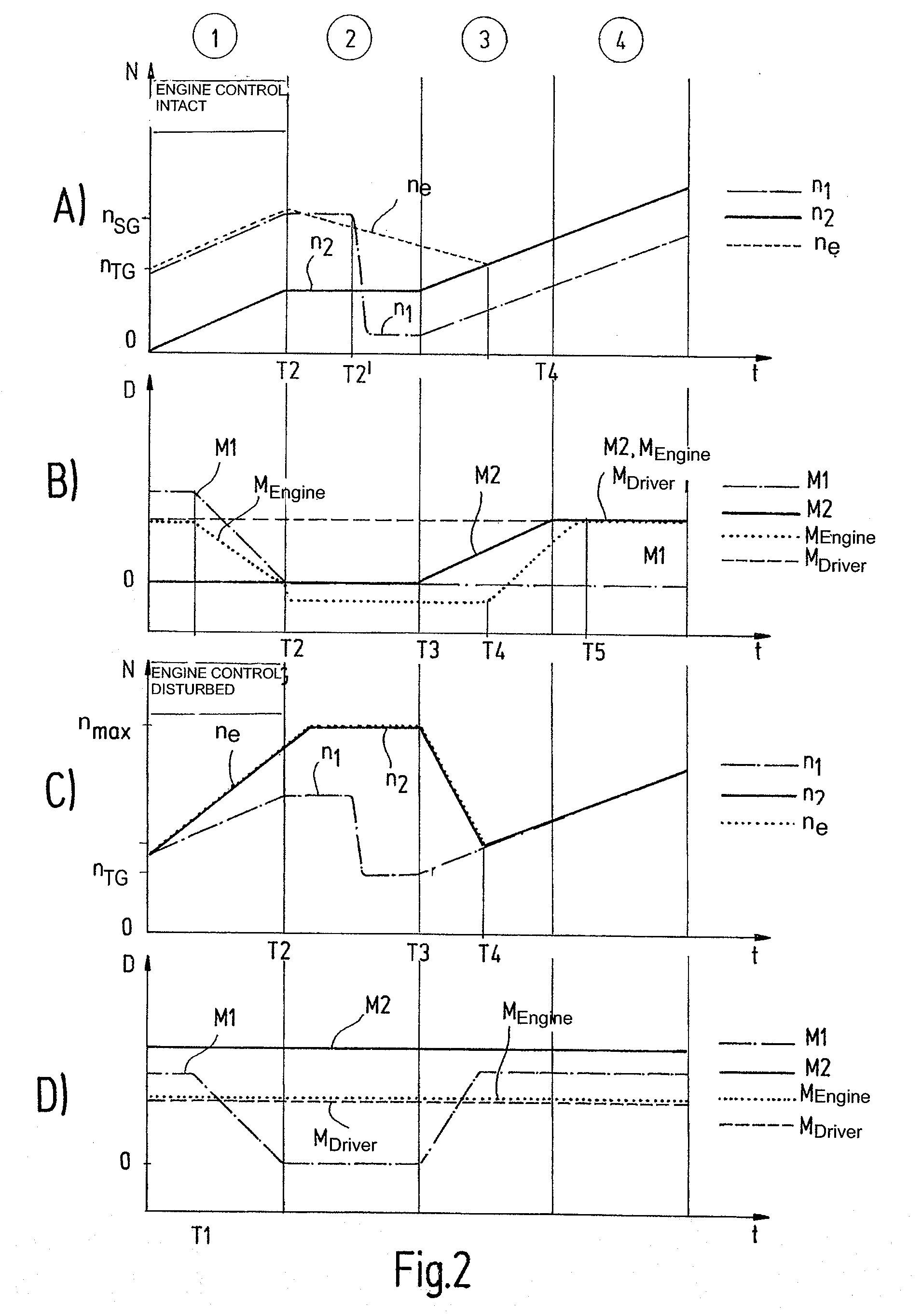
In this manner, it is possible to gain information on the number of revolutions of the engine, although the sensor dedicated to this purpose fails, or the data bus connection between the engine control and the clutch and transmission control fails.

Method used


Image

  • System and method for operating a dual clutch transmission during failure of an engine speed sensor or a bus connection between control modules
  • System and method for operating a dual clutch transmission during failure of an engine speed sensor or a bus connection between control modules
  • System and method for operating a dual clutch transmission during failure of an engine speed sensor or a bus connection between control modules

Examples


Embodiment Construction

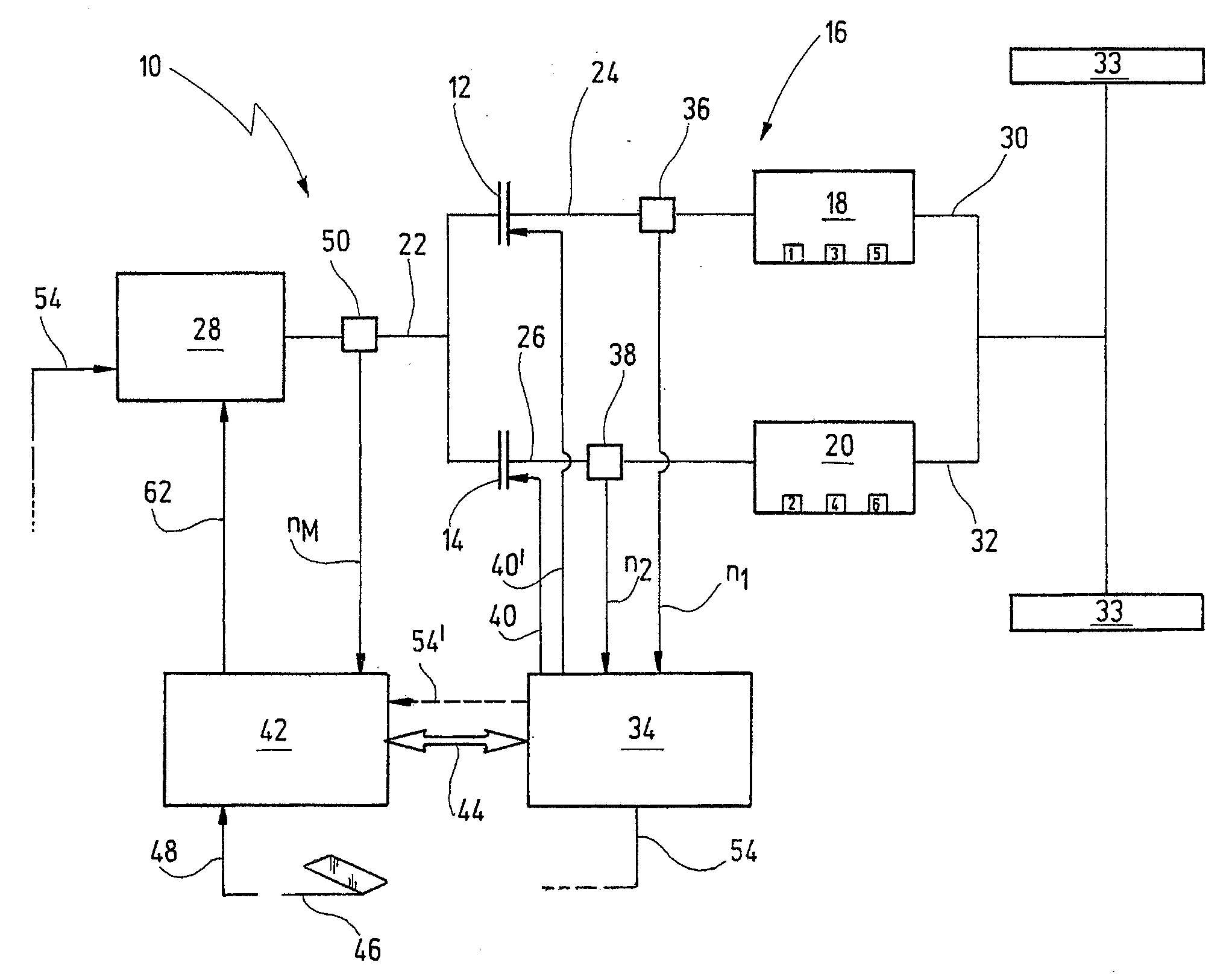
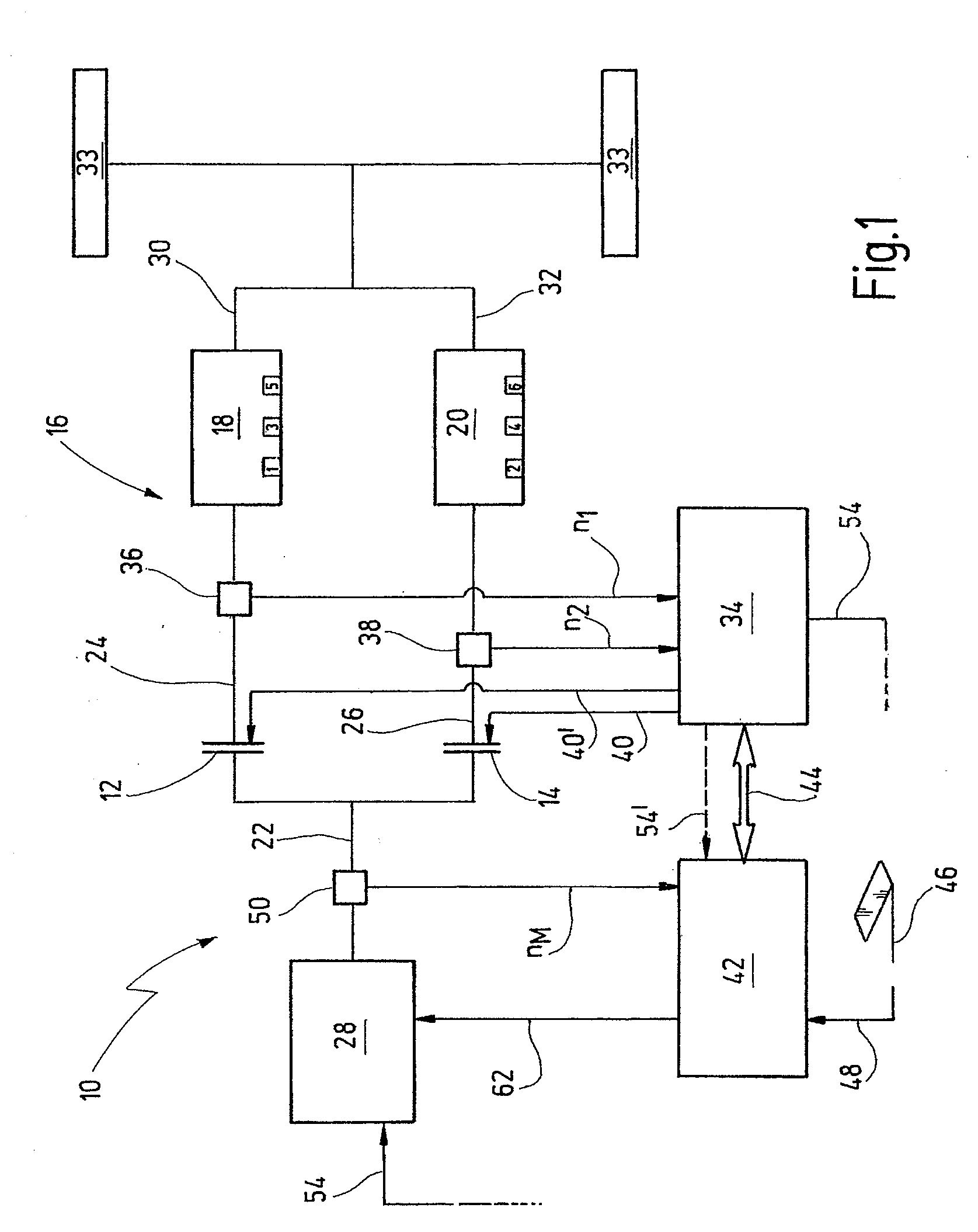
[0029]FIG. 1 shows a simplified drive line 10 of a motor vehicle having a dual clutch transmission 16.

[0030]The drive line 10 comprises two friction clutches 12, 14 which function as separation and starting clutches dedicated to a first partial transmission 18 and a second partial transmission 20. Here, the first partial transmission 18 exemplarily represents the first, third and fifth gear. Here, the second partial transmission 20 exemplarily represents the second, fourth and sixth gear, respectively. Although here a dual shift transmission is shown, the following explanations and concepts can also be used with single shift gears, if correspondingly adapted.

[0031]The separation clutches 12, 14 are simple friction clutches, each of which can be actuated by means of a clutch actuator which is not shown in greater detail. In a closed position, the first separation clutch 12 connects an engine output shaft 22 in a friction-locked manner to a first transmission input shaft 24. This also...


PUM


Abstract

It is disclosed a system and method for maintaining the operation of an automated transmission (16), particularly a dual clutch transmission, for a motor vehicle, in case of a failure of an engine speed sensor (50) or a bus connection (44) between a first control module (42) controlling an engine (28) being connectable to the transmission (16) through at least one separation clutch (12, 149, and a second control module (34) controlling regulating units (12, 14) for connecting the engine (28) to the transmission (16) or to one or more driving wheels (34) in a force-transmitting manner, wherein gear-shift relevant data, particularly a number of revolutions (ne) of the engine, is exchanged between the control modules (34, 42) over the bus connection (44), the method comprising the following steps: checking whether a number of revolutions (ne; n1, n2) of a shaft (22; 30, 32, particularly an engine shaft (22), which is detected by a sensor (50) of one of the control modules (42) dedicated to this purpose can be transmitted from the one of the control modules (34, 42) via the bus connection (44) to the other one of the control modules (42, 34); and performing the following steps, if the number of revolutions cannot be transmitted: opening all synchronizer devices assigned to the transmission (16) or one of the partial transmissions (18, 20) so that the engine shaft (22) can no longer transmit force via a transmission shaft to the driving wheels (33) of the motor vehicle; closing the separations clutch (12, 14) assigned to the transmission (16) or the partial transmission (18, 20) by means of the opened synchronizer devices, if this separation clutch (12, 14) is not closed; detecting a number of revolutions (n1, n2; ne) of another shaft (24, 26), particularly the transmission shaft, which can be connected to the shaft (22) through the separation clutch (12, 14) by means of a sensor (36, 38) of another control module (34), wherein the sensor (36, 38) is dedicated to this purpose; and determining a gear-shift ramp function for one of the control modules (34, 42), preferably the second control module (42), based on the detected number of revolutions, particularly from a field of characteristic lines, for allowing performance of a shifting process from a source gear to a target gear (FIG. 4).

Description

CROSS-REFERENCE TO RELATED APPLICATIONS[0001]This application claims the priority of the German patent application DE 10 2008 027 675 filed on Jun. 3, 2008 which is fully incorporated by reference herewith.BACKGROUND OF THE INVENTION[0002]The present invention relates to a system and method for continuing the operation of an automated transmission of a motor vehicle, when a engine speed sensor or a data connection fails in terms of a data bus line between at least two control modules controlling cooperating components of a drive line and exchanging gear-shift relevant data between each other through the bus.RELATED PRIOR ART[0003]Different components of conventional automated transmissions of motor vehicles, such as an engine and a transmission, are typically controlled by different control modules, which can also be implemented in terms of a central control device. Particularly, dual clutch transmissions require a corresponding electronic control for ensuring the complex and diffic...

Claims


Application Information

Patent Timeline
IPC IPC(8): G06F19/00F16H61/12
CPCY10T477/688Y10T477/675F16H61/682F16H2061/1284F16H61/12F16H2061/1224F16H61/688
Inventor GLATTHAAR, JOSEFKALISCH, TOBIASOTTINGER, OLIVERPALANSKY, BRUCE
Owner GETRAG GETRIEBE & ZAHNRADFABRIK HERMANN HAGENMEYER GMBH & CO KG
Why Eureka
Eureka Blog
Learn More