Labyrinth seal and method of producing a labyrinth seal

Inactive Publication Date: 2010-09-30
AB SKF
View PDF6 Cites 7 Cited by
  • Summary
  • Abstract
  • Description
  • Claims
  • Application Information

AI Technical Summary

Benefits of technology

[0028]Recesses for holding encoder devices may be formed in the second disc. The encoder devices can then be inserted into said recesses, and the labyrinth seal can thus perform an encoder function in addition to its sealing function. Furthermore, curved slots can be formed in the first disc and/or in the second disc. At least one of the rings can then be fastened to at least one of the discs by virtue of the projections of said ring being plugged into the slots of the disc. In this way, the respective ring is placed into a round shape in a very simple manner with a degree of precision predefined by the slots. Complex measurement and alignment processes may be dispensed with. It is additionally or alternatively possible for the ring to be fixed to the disc in particular in a material bonded manner (e.g., by welding, adhesives, etc).
[0029]The formation of the slots and/or the recesses for the encoder devices can be carried out by means of a laser beam. This may take place before or after the detachment from the sheet of material. In this working step, too, the use of a laser beam provides considerable advantages in relation to alternative methods. Using the laser beam, the desired contours can be generated with a very high degree of precision quickly and with relatively little expenditure. This has the result, for example, that the slots lay on a common circular line with a high degree of precision. It is therefore possible for the ring to be placed into a round shape with a very high degree of precision as the projections of the respective ring are plugged into the slots. The production of the slots by means of a laser beam, the plugging of the projections of the rings into the slots and the subsequent laser welding therefore constitute a virtually ideal combination by means of which the sealing labyrinth can be produced wit

Problems solved by technology

However, a labyrinth seal generally has a relatively complex shape because, to obtain a good sealing action, it is necessary to form as convoluted a path as possible, which is also referred to as a sealing labyrinth, between the regions to be sealed off with respect to one another.
However, with increasing size, the limited

Method used


Image

  • Labyrinth seal and method of producing a labyrinth seal
  • Labyrinth seal and method of producing a labyrinth seal
  • Labyrinth seal and method of producing a labyrinth seal

Examples


Example

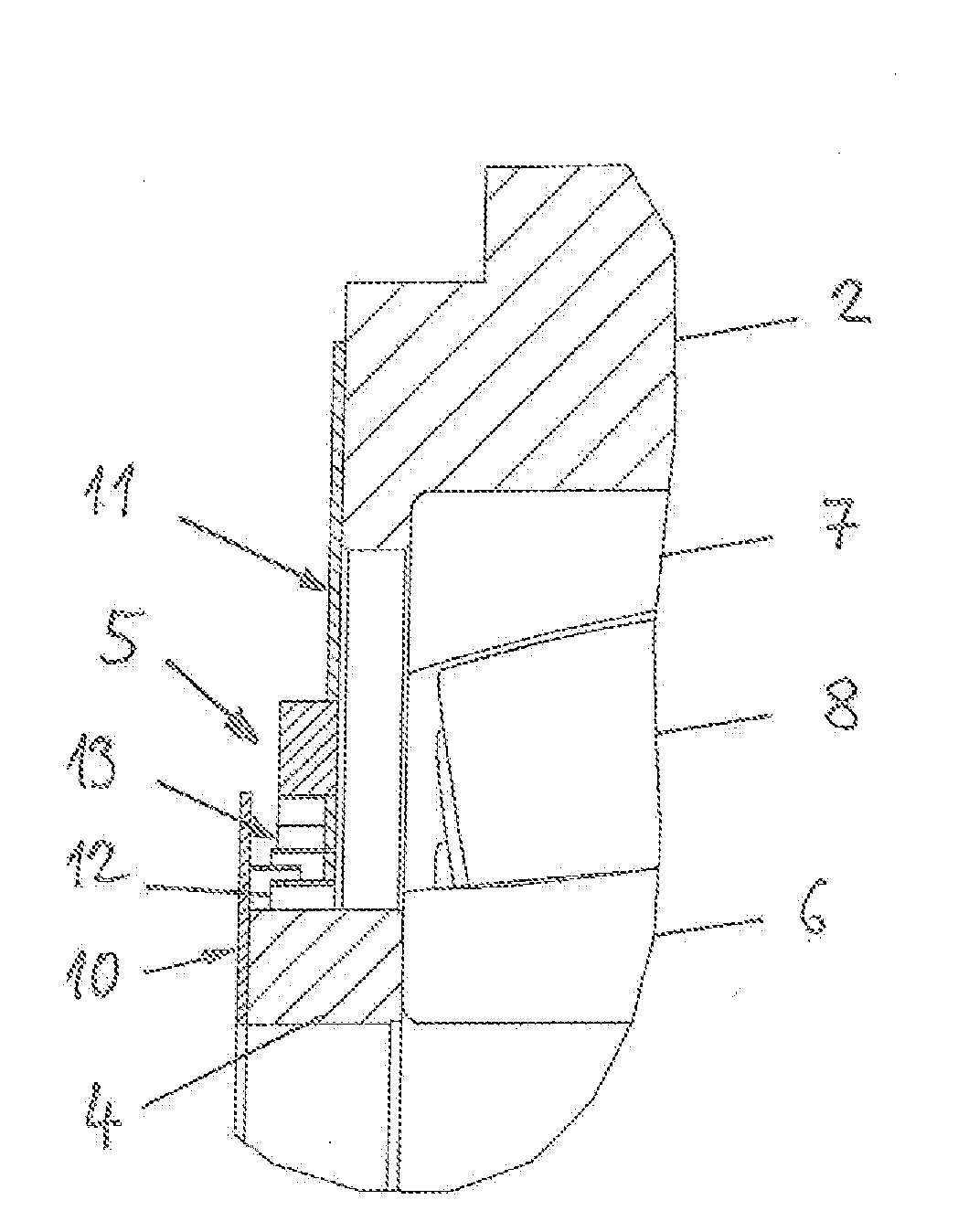
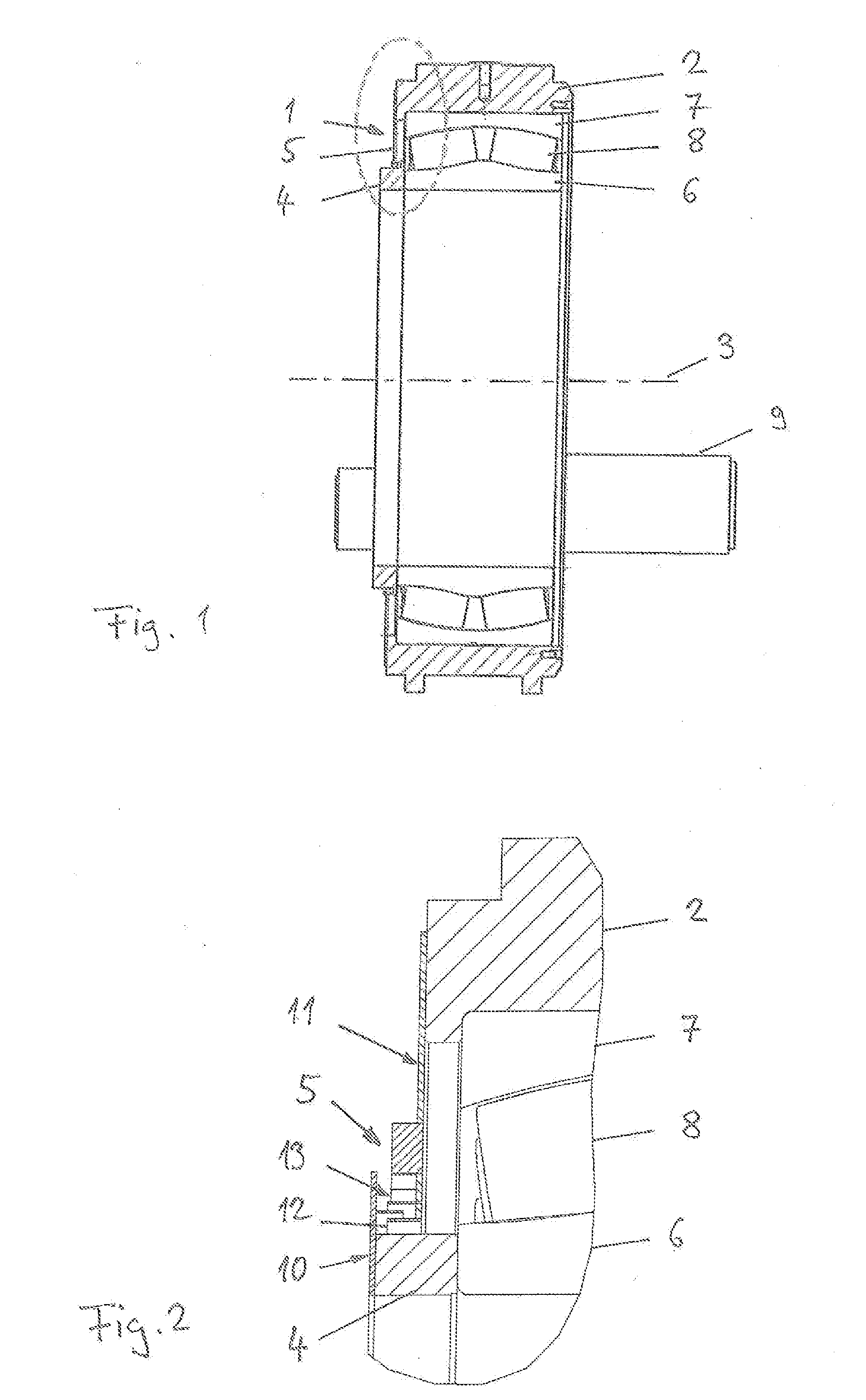
[0045]FIG. 1 shows an exemplary embodiment of a bearing arrangement designed according to the invention. The bearing arrangement has a rolling bearing 1 which, in the illustrated exemplary embodiment, is designed as a double-row spherical roller bearing. The rolling bearing 1 may for example also be designed as a double-row tapered roller bearing or have some other single-row or multi-row design. The rolling bearing 1 is arranged in a housing 2 and serves to mount a machine part which is not illustrated in the Figs., for example a shaft, such that said machine part is rotatable about an axis of rotation 3. The rolling bearing 1 may be fastened to the mounted machine part by means of a clamping nut 4. A labyrinth seal 5 attached to the housing 2 and to the clamping nut 4 seals off the bearing arrangement on one axial side. The axial direction is considered in each case to be a direction parallel to the axis of rotation 3 of the rolling bearing 1 unless stated otherwise.

[0046]The roll...


PUM

PropertyMeasurementUnit
Diameteraaaaaaaaaa

Abstract

A labyrinth seal includes a first disc and a second disc spaced axially from the first disc such that an axial intermediate chamber is formed between the first and the second discs. A first ring connected with the first disc so as to extend generally toward the second disc and into the axial chamber and second and third rings are each connected with the second disc so as to extend generally toward the first disc and into the axial chamber. The third ring is spaced radially outwardly from the second ring and the first ring being at least partially disposed radially between the second and third rings so as to form a sealing labyrinth. Preferably, each of the rings is cut from a common strip of material, bended to form a ring and welded to the associated disc.

Description

[0001]The present application claims priority to German Patent Application No. 10 2009 009 226.9 filed on Feb. 17, 2009, the contents of which are fully incorporated herein by reference.[0002]The present invention relates to seals, more particularly to labyrinth seals for sealing bearings.[0003]A labyrinth seals are generally known and can be used, for example, to seal off a housing with respect to a shaft. Sealing by means of a labyrinth seal has the advantage that the labyrinth seal is not subjected to wear, in contrast to a sliding seal. However, a labyrinth seal generally has a relatively complex shape because, to obtain a good sealing action, it is necessary to form as convoluted a path as possible, which is also referred to as a sealing labyrinth, between the regions to be sealed off with respect to one another. A sealing labyrinth may for example be realized by means of two or more complementarily formed components which engage one into the other in a comb-like manner. The co...

Claims


Application Information

Patent Timeline
IPC IPC(8): F16J15/447F16C33/72F16C33/80B23P17/04
CPCF16C33/7806F16C33/7886F16C33/80Y10T29/49826F16C2360/31F16C23/086F16J15/4472F16C2300/14F16C19/38F16C2226/36
Inventor HORLING, PETERKAMM, SANDRAKERN-TRAUTMANN, ANDREASLIESEGANG, HANS-JURGENWAGNER, REINER
Owner AB SKF
Why Eureka
Try Eureka