
Vertical wind turbine

a vertical wind turbine and wind farm technology, applied in the direction of machines/engines, liquid fuel engines, electric generator control, etc., can solve the problems of unsightly and unaesthetically pleasing wind farms, and many aesthetical objections to the use of pedestal mounted turbines, so as to improve efficiency, reduce friction, and be easily mounted in or on a single structure

Inactive Publication Date: 2010-09-30
DORNAN MARK
View PDF10 Cites 25 Cited by
  • Summary
  • Abstract
  • Description
  • Claims
  • Application Information

AI Technical Summary

Benefits of technology

[0012]A still further object of the present invention is to provide for a novel vertical wind turbine in which the internal turbine blades are mounted so as to magnetically float to reduce friction and improve efficiency.
[0013]A still further object of the present invention is to provide for a novel vertical wind turbine which is aesthetically pleasing to the eye.
[0014]A still further object of the present invention is to provide for a novel vertical wind turbine which presents no danger to bird life.
[0015]A still further object of the present invention is to provide for a novel vertical wind turbine which can easily be mounted in or on a single structure, such as a house or office building for the generation of electricity for the particular structure.
[0016]A still further object of the present invention is to provide for a novel vertical wind turbine which can be mounted in or on an electric or hybrid vehicle so as to recharge the batteries of the vehicle while the vehicle is moving, thus extending the distance which the electric or hybrid vehicle can travel.SUMMARY OF THE INVENTION
[0017]A vertical wind turbine rotatable on its vertical axis in order to capture the most direct vector of the wind, the vertical wind turbine having a horizontal inlet port in communication with a vertical air shaft within which is mounted a vertical shaft having a plurality of horizontally disposed wind turbine blades, the lower end magnetically floating to reduce friction, the lower portion of the vertical wind turbine shaft in intersecting communication with one or more horizontal shafts having a venturi design so as to draw a partial vacuum or low pressure, enhancing the downward flow of the air in the vertical wind turbine, the vertical wind turbine in communication with a generator for the production of electricity, the vertical wind turbine being rotatably but stationary mounted on a stationary object or fixedly mounted on a vehicle with the inlet port of the vertical wind turbine forwardly facing.

Problems solved by technology

However, many view these wind farms as unsightly and not aesthetically pleasing.
The main limitation on electric and hybrid vehicles is that the vehicles will only allow travel of a specific distance on the batteries alone before a recharge is required.
Still further, many aesthetical objections remain to the use of pedestal mounted turbines.

Method used


Image

  • Vertical wind turbine
  • Vertical wind turbine
  • Vertical wind turbine

Examples


Embodiment Construction

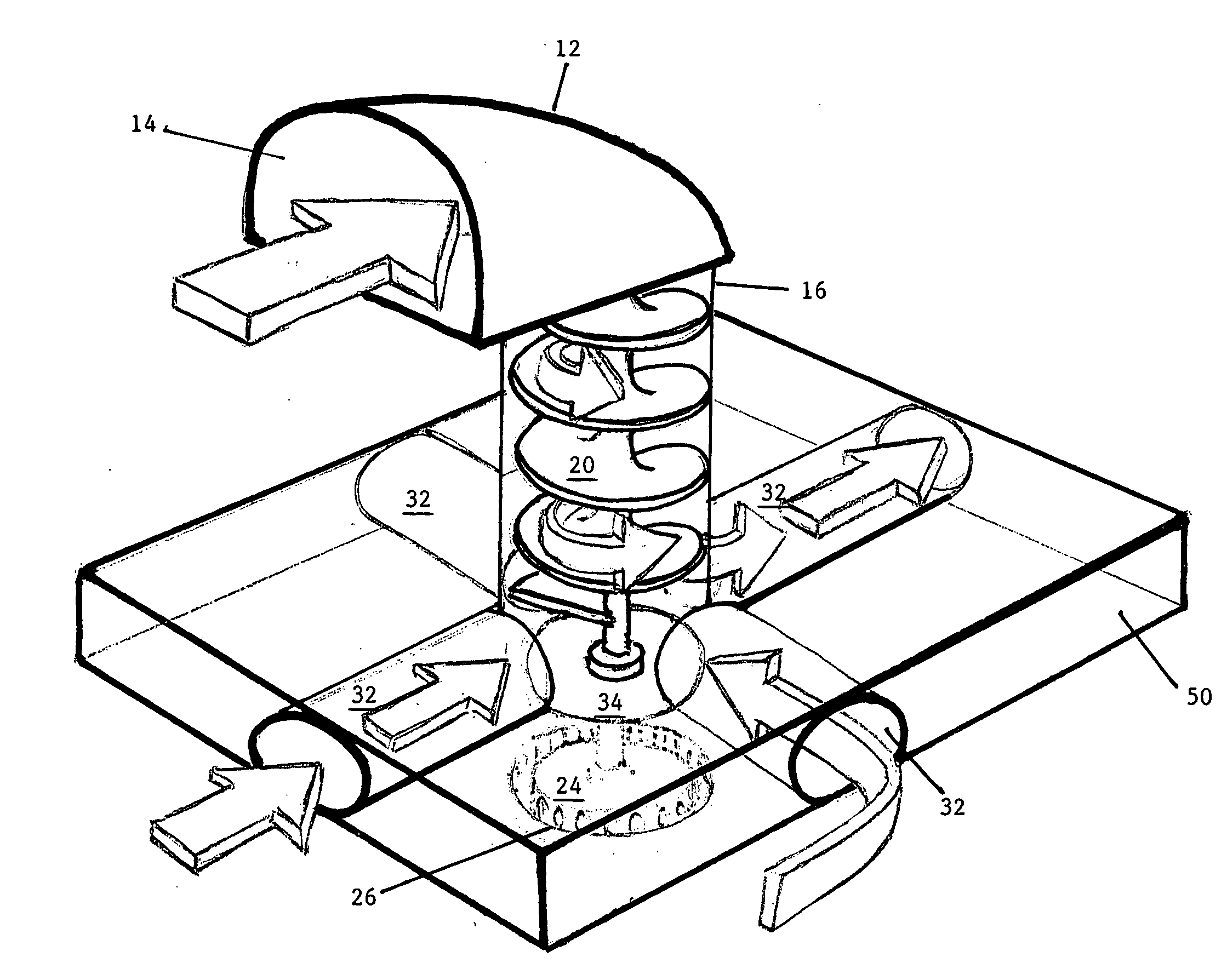
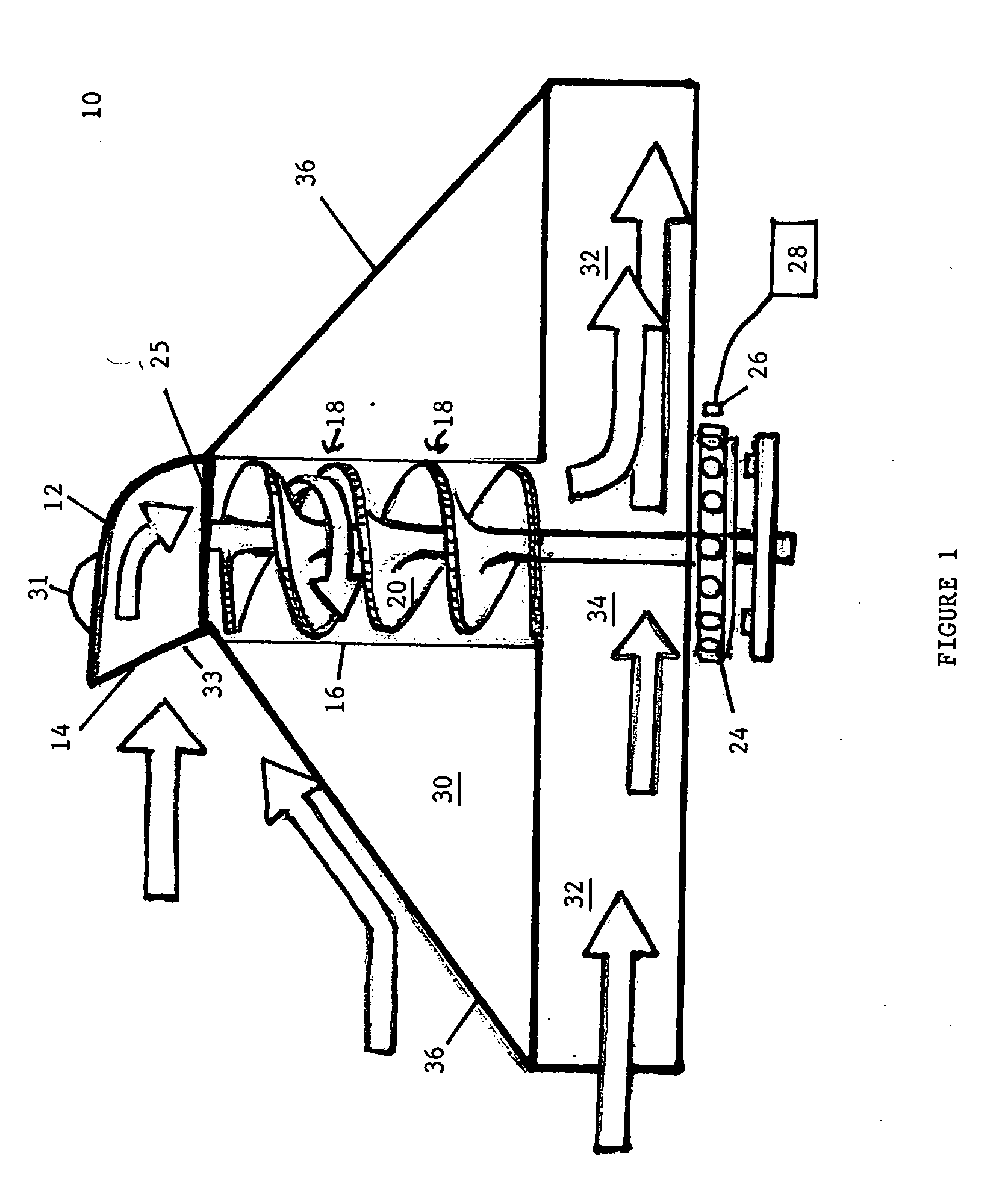
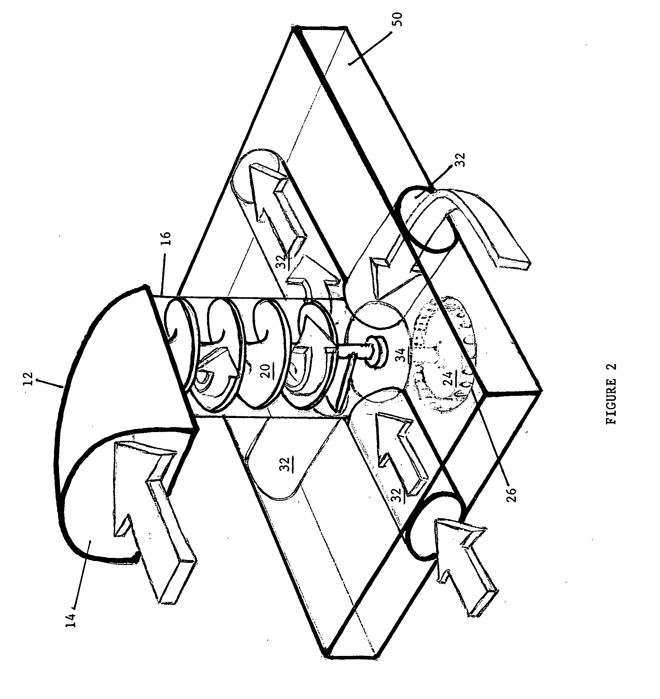
[0023]FIG. 1 is illustrative of the basic structure of the vertical wind turbine 10 of the present invention. Vertical wind turbine 10 has an upper intake manifold 12 having a generally horizontal intake port 14. Intake manifold 12 could be characterized as L-shaped in configuration in that it transforms a horizontal wind vector into a vertical wind vector directing the wind vector downwardly into a vertical downspout or air shaft 16, which is preferably cylindrical in cross-section, but may be formed in a truncated conical section 17 or an inverted truncated conical section 19 (FIGS. 5 and 6).

[0024]Mounted within vertical downspout 16 are a plurality of wind turbines 18, the blades 20 of which are mounted to a centrally disposed vertical shaft 22, the lower end 21 of which is mounted on a magnetically supported disk 24 thereby allowing the centrally mounted rotatable shaft 22 and wind turbine blades 20 mounted thereon to float and to rotate with a minimum of friction. The upper end...


PUM


Abstract

A vertical wind turbine rotatable on its vertical axis in order to capture the most direct vector of the wind, the vertical wind turbine having a horizontal inlet port in communication with a vertical air shaft within which mounted vertically, a shaft having a plurality of horizontally disposed wind turbine blades, the lower end magnetically floating to reduce friction, the lower portion of the vertical wind turbine shaft in intersecting communication with one or more horizontal shafts having a venturi design so as to draw a partial vacuum or low pressure, enhancing the downward flow of the air in the vertical wind turbine, the vertical wind turbine in communication with a generator for the production of electricity, the vertical wind turbine being rotatably but stationary mounted on a stationary object or fixedly mounted on a vehicle with the inlet port of the vertical wind turbine forwardly facing.

Description

RELATED APPLICATIONS[0001]Applicant claims the benefit of provisional application Ser. No. 61 / 211,281, filed Mar. 27, 2009.BACKGROUND OF THE INVENTION[0002]1. Field of the Invention[0003]The present invention relates to the field of wind turbines as an alternative energy source, and more particularly, to an aesthetically pleasing wind turbine which functions in a vertical orientation, either stationary or on a vehicle.[0004]2. Description of the Prior Art[0005]Wind turbines or their equivalence, have been in use for hundreds of years. The earliest wind turbine, the windmill, converted wind energy into mechanical energy, normally to pump water. The fluctuation of petroleum prices and the popular ethic of “going green” has led to the development of wind turbines for the production of electricity. Vast areas of North America and other continents have prevailing wind patterns which makes these areas suitable for the establishment of wind farms with many pedestal mounted wind turbines co...

Claims


Application Information

Patent Timeline
Patent Type & Authority Applications(United States)
IPC IPC(8): F03D9/00F04D29/44F03B17/04
CPCF03D9/00F05B2240/13F05B2240/211Y02E10/72F05B2250/25Y02B10/30F05B2240/941Y02E10/728F03D1/02F03D1/04F03D9/25F03D9/32F03D9/34
Inventor DORNAN, MARK
Owner DORNAN MARK
Learn More