

Method for feeding electric power to a planar light-emitting element
a technology of electric power and light-emitting elements, which is applied in the direction of electroluminescent light sources, semiconductor lamp usage, organic semiconductor devices, etc., can solve the problems of difficult to completely prevent the occurrence of electric potential gradients, complicated power feeding circuits, and inability to adjust the color of light-emitting surfaces
- Summary
- Abstract
- Description
- Claims
- Application Information
AI Technical Summary
Benefits of technology
Problems solved by technology
Method used
Image

Examples
first embodiment
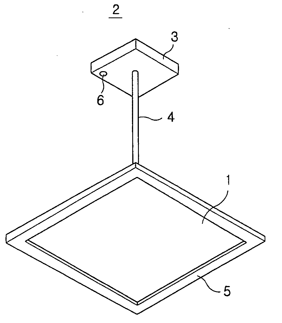
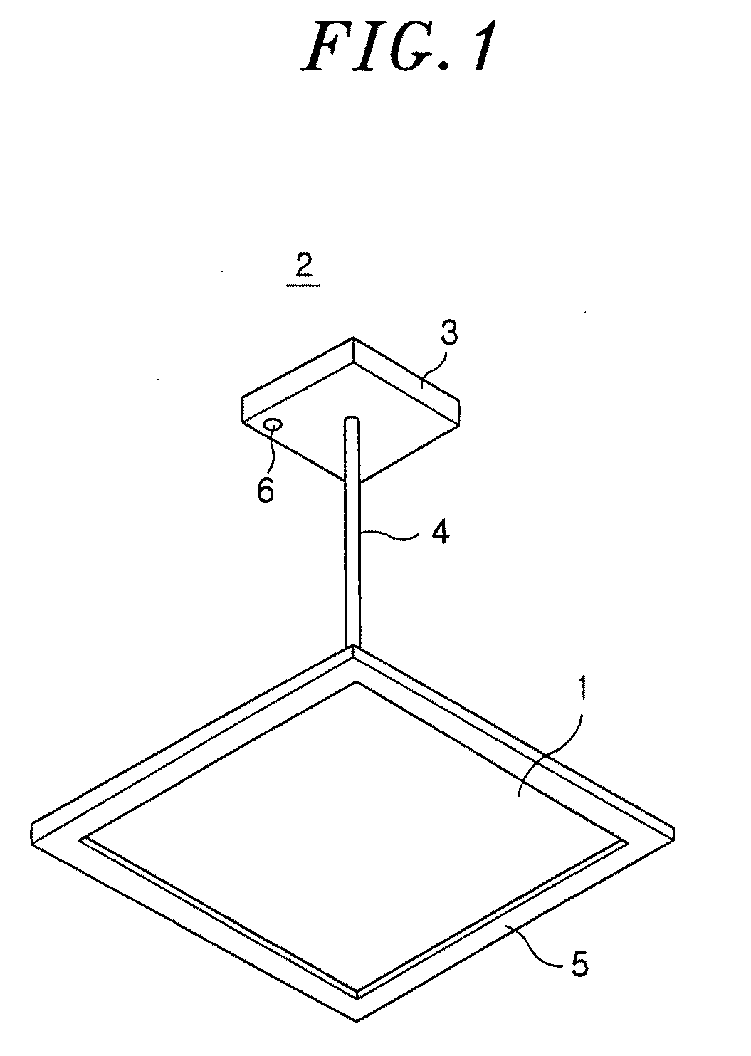
[0047]FIG. 1 shows an illumination device 2 provided with a planar light-emitting element 1 (hereinafter simply referred to as “light-emitting element”) in accordance with a first embodiment of the present invention. The illumination device 2 includes a light-emitting element 1, a suspender mechanism 3 for attaching the light-emitting element 1 to a ceiling and a power cord 4 for interconnecting the light-emitting element 1 and the suspender mechanism 3. A periphery of the light-emitting element 1 is covered and protected by a lamp case 5. The suspender mechanism 3 is provided on its surface with a signal receiving portion 6 for receiving a remote control signal transmitted from a remote controller (not shown).
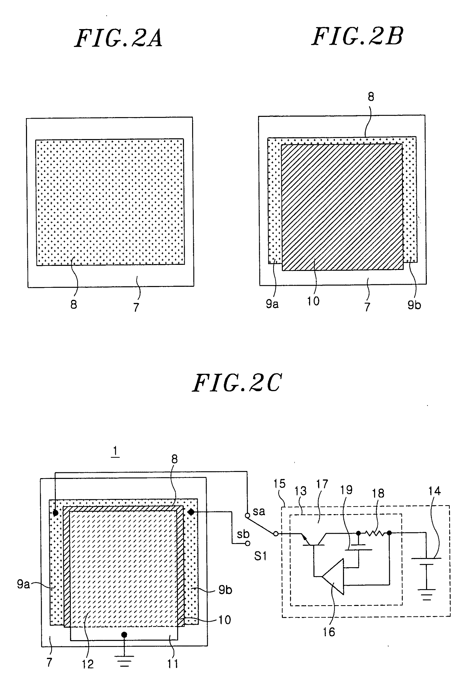
[0048]The light-emitting element 1 is produced in the following order. Referring to FIG. 2A, a rectangular planar anode electrode 8 (hereinafter simply referred to as “anode”) is first formed on a rectangular base 7. Then, a rectangular light-emitting layer 10 is formed on the...
second embodiment
[0065]FIG. 7 shows a light-emitting element in accordance with a second embodiment of the present invention. The light-emitting element 41 differs from the light-emitting element 1 of the first embodiment in that it includes three anode terminal portions 9a, 9b and 9c. Other configurations remain the same. The light-emitting element 41 includes three anode terminal portions 9a, 9b and 9c protruding from three sides of the anode 8 and a cathode terminal portion 11 protruding from one side of the cathode 12. The anode terminal portion 9a is arranged in an opposing relationship with the anode terminal portion 9c, while the anode terminal portion 9c is arranged in an opposing relationship with the cathode terminal portion 11.
[0066]In the light-emitting element 41, the anode terminal portions 9a, 9b and 9c are electrically connected to the constant current circuit 13 and the power source 14 through a switch S2, the cathode terminal portion 11 being grounded. The switch S2 includes a term...
third embodiment
[0077]FIG. 12 shows a light-emitting element 44 in accordance with a third embodiment of the present invention. The light-emitting element 44 of the present embodiment differs from that of the first embodiment in that a pair of anode terminal portions 9a and 9b is provided in specified positions. Other configurations remain the same. The anode terminal portions 9a and 9b are provided in pair near the intersecting points between line h1-h2 passing through the center G of the light-emitting layer 10 and the periphery portions of the light-emitting element 44.
[0078]The cathode terminal portion 11 is provided in a position equally spaced apart from the anode terminal portions 9a and 9b. In other words, the distance between the center C1 of the anode terminal portion 9a and the center C3 of the cathode terminal portion 11 is equal to the distance between the center C2 of the anode terminal portion 9b and the center C3 of the cathode terminal portion 11. The line passing through the cente...
PUM
 Abstract
Description
Claims
Application Information