Voltage-controlled oscillator, and pll circuit, fll circuit, and wireless communication device using the same

a voltage control and oscillator technology, applied in the direction of oscillator generators, pulse automatic control, pulse techniques, etc., can solve the problem of almost completely unnecessary control of the control voltag

Active Publication Date: 2010-09-30
PANASONIC CORP
View PDF1 Cites 14 Cited by
  • Summary
  • Abstract
  • Description
  • Claims
  • Application Information

AI Technical Summary

Benefits of technology

[0007]Hence, an objective of the present invention is to provide a voltage-controlled oscillator that can hold an oscillation frequency at a desired value when the oscillation frequency changes due to th

Problems solved by technology

Therefore, it is almost completely unnecessary to control

Method used


Image

  • Voltage-controlled oscillator, and pll circuit, fll circuit, and wireless communication device using the same
  • Voltage-controlled oscillator, and pll circuit, fll circuit, and wireless communication device using the same
  • Voltage-controlled oscillator, and pll circuit, fll circuit, and wireless communication device using the same

Examples


first embodiment

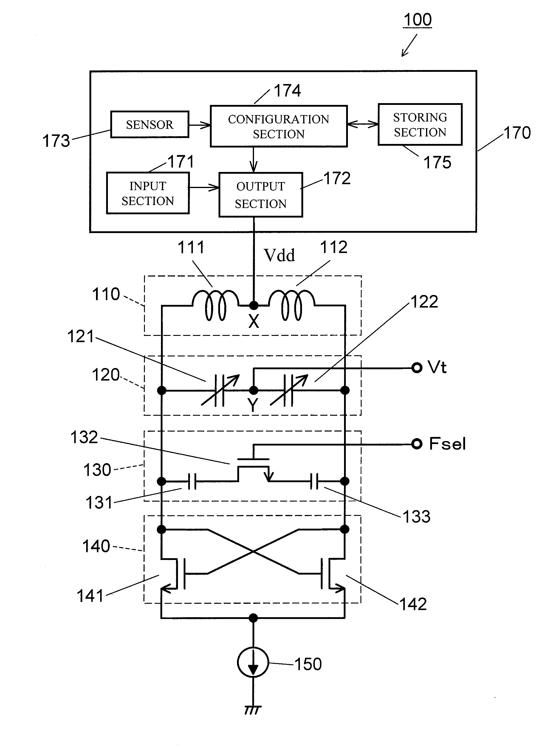
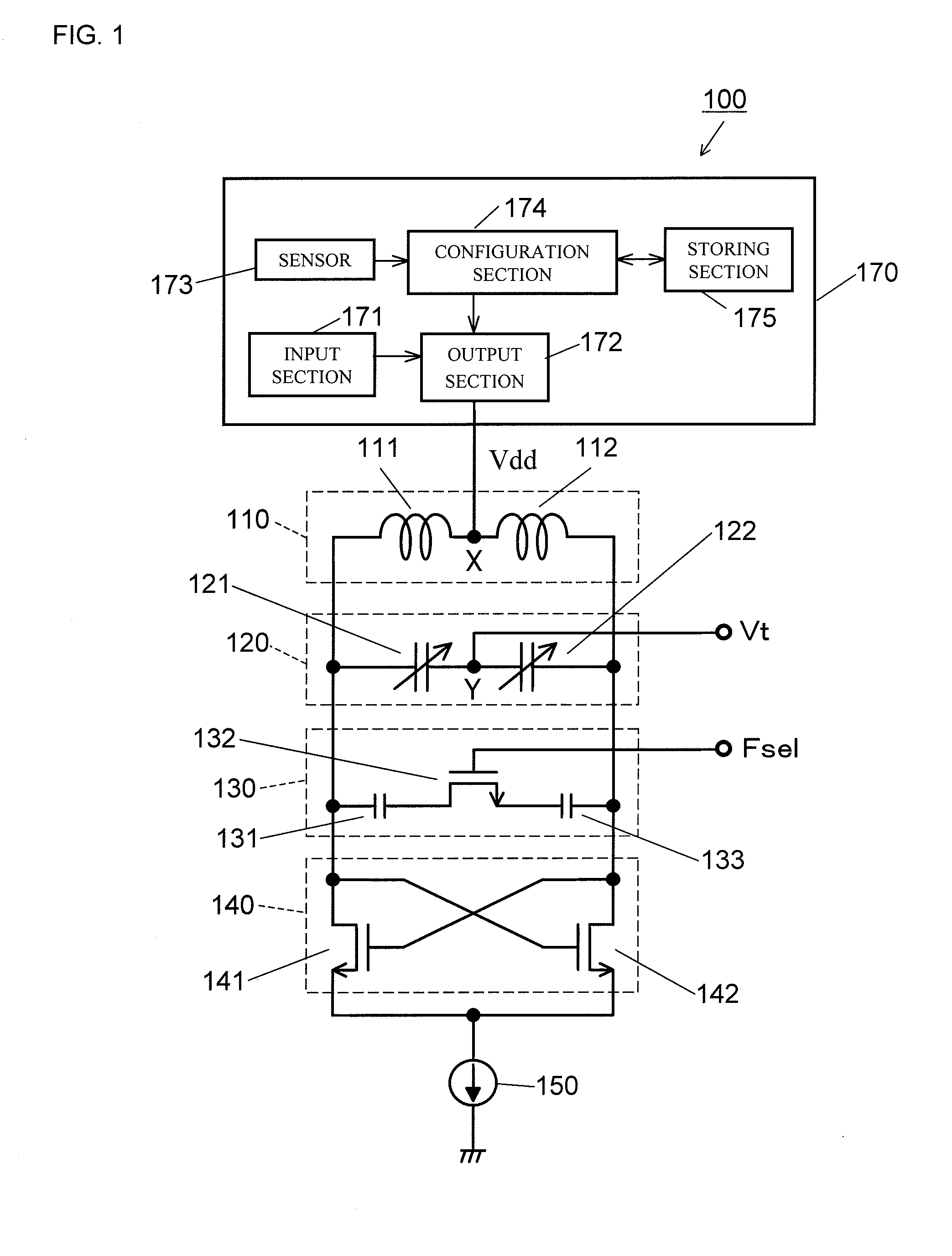
[0036]A first embodiment of the present invention will be described with reference to drawings as appropriate in the following. FIG. 1 is a figure showing a configurational example of a voltage-controlled oscillator 100 according to the first embodiment. The voltage-controlled oscillator 100 is a device that generates a local oscillation signal of a wireless communication device such as a mobile phone and the like. As shown in FIG. 1, the voltage-controlled oscillator 100 includes: an inductor circuit 110; a variable capacitance circuit 120; a capacitance switching circuit 130; a negative resistance circuit 140; a current source 150; and a control section 170. The inductor circuit 110, the variable capacitance circuit 120, the capacitance switching circuit 130, and the negative resistance circuit 140 are parallelly connected to each other. Described in the present embodiment is the voltage-controlled oscillator 100 having a configuration in which a single capacitance switching circu...

second embodiment

[0056]A second embodiment of the present invention will be described in the following. FIG. 8 is a figure showing a configurational example of a voltage-controlled oscillator 200 according to the second embodiment of the present invention. The voltage-controlled oscillator 200 has a configuration similar to that of the voltage-controlled oscillator 100, except for having a low-dropout regulator (LDO) 190 instead of the control section 170 (refer FIG. 1). Thus, descriptions of the configurations that are common with the voltage-controlled oscillator 100 are omitted in the second embodiment. The buffer amplifiers 181 and 182 are omitted from FIG. 8.

[0057]The power-supply voltage Vdd is applied to the connection point X between the inductors 111 and 112 by the low-dropout regulator 190. FIG. 9 is a figure showing one example of a circuit configuration of the low-dropout regulator 190. The low-dropout regulator 190 includes: resistances 191, 192, and 193; PNP type transistors 194 and 19...


PUM


Abstract

Provided is a voltage-controlled oscillator that can hold an oscillation frequency at a desired value when an oscillation frequency changes due to the temperature, without narrowing a variable range of the oscillation frequency, and a PLL circuit, an FLL circuit, and a wireless communication device, which use the voltage-controlled oscillator. A control voltage Vt is applied to a connection point Y between variable capacitors 121 and 122 included in a variable capacitance circuit 120. A control signal Fse1 is applied to a switching element 132 included in a capacitance switching circuit 130. A power-supply voltage Vdd is applied by a control section 170 to a connection point X between inductors 111 and 112 included in an inductor circuit 110. A voltage value of the power-supply voltage Vdd is controlled such that the oscillation frequency of the local oscillation signal is held at a constant regardless of a temperature change.

Description

BACKGROUND OF THE INVENTION[0001]1. Field of the Invention[0002]The present invention relates to a voltage-controlled oscillator (VCO) that is used in a wireless communication device, and a PLL circuit, an FLL circuit, and a wireless communication device, all of which use the voltage-controlled oscillator.[0003]2. Description of the Background Art[0004]Conventionally, a voltage-controlled oscillator is widely used as a device for generating a local oscillation signal of a wireless communication device. FIG. 12 is a figure showing a configurational example of a conventional voltage-controlled oscillator. The voltage-controlled oscillator shown in FIG. 12 includes: two inductors 11 and 12; two variable capacitors 21 and 22; a switching element 32; two capacitive elements 31 and 33; two oscillation transistors 41 and 42; and a current source 50. A constant power-supply voltage Vdd is applied to a connection point between the inductors 11 and 12 by an LDO (low-dropout regulator). In add...

Claims


Application Information

Patent Timeline
IPC IPC(8): H03L7/06H03B5/12
CPCH03L1/022H03L7/099H03B5/1228H03B5/1293H03B5/1243H03B5/1265H03B5/1253H03B5/1215
Inventor TSUKIZAWA, TAKAYUKI
Owner PANASONIC CORP
Why Eureka
Try Eureka