Circularly polarized antenna for satellite communication

a satellite communication and circular polarization technology, applied in the structural form of radiating elements, resonant antennas, substantially flat resonant elements, etc., can solve the problems of narrow impedance bandwidth, heavy weight and large volume of metal waveguides, and the inability to realize multi-feed array antennas, etc., to achieve the effect of broadening the impedance bandwidth, reducing the loss of feed, and improving the transmission efficiency

Inactive Publication Date: 2010-09-30
IND UNIV COOP FOUND KOAEA AEROSPACE UNIV
View PDF3 Cites 69 Cited by
  • Summary
  • Abstract
  • Description
  • Claims
  • Application Information

AI Technical Summary

Benefits of technology

[0013]It is another object of the present invention to provide a circularly polarized antenna for satellite communication, which can minimize feed loss in a high frequency band of satellite communication and can broaden an impedance bandwidth via integration of an impedance matching network and circular polarization.
[0014]It is a further obj...

Problems solved by technology

However, the metal waveguide has disadvantages of a heavy weight and large volume.
Another disadvantage of the disclosed antenna is a narrow impedance bandwidth due to the absence of an impedance matching network.
In this case, it is impossible to realize a multi-feed array antenna because all spaces are sheltered by a via array defining a cyli...

Method used


Image

  • Circularly polarized antenna for satellite communication
  • Circularly polarized antenna for satellite communication
  • Circularly polarized antenna for satellite communication

Examples


Embodiment Construction

[0040]Hereinafter, a detailed description of a preferred embodiment of the present invention with reference to the accompanying drawings is as follows. In the following description, a detailed description of known functions and configurations incorporated herein will be omitted when it may make the subject matter of the present invention rather unclear.

[0041]In the drawings, it is noted that the same or similar elements are denoted by the same reference numerals even though they are depicted in different drawings. Now, the preferred embodiment of the present invention will be described with reference to the accompanying drawings.

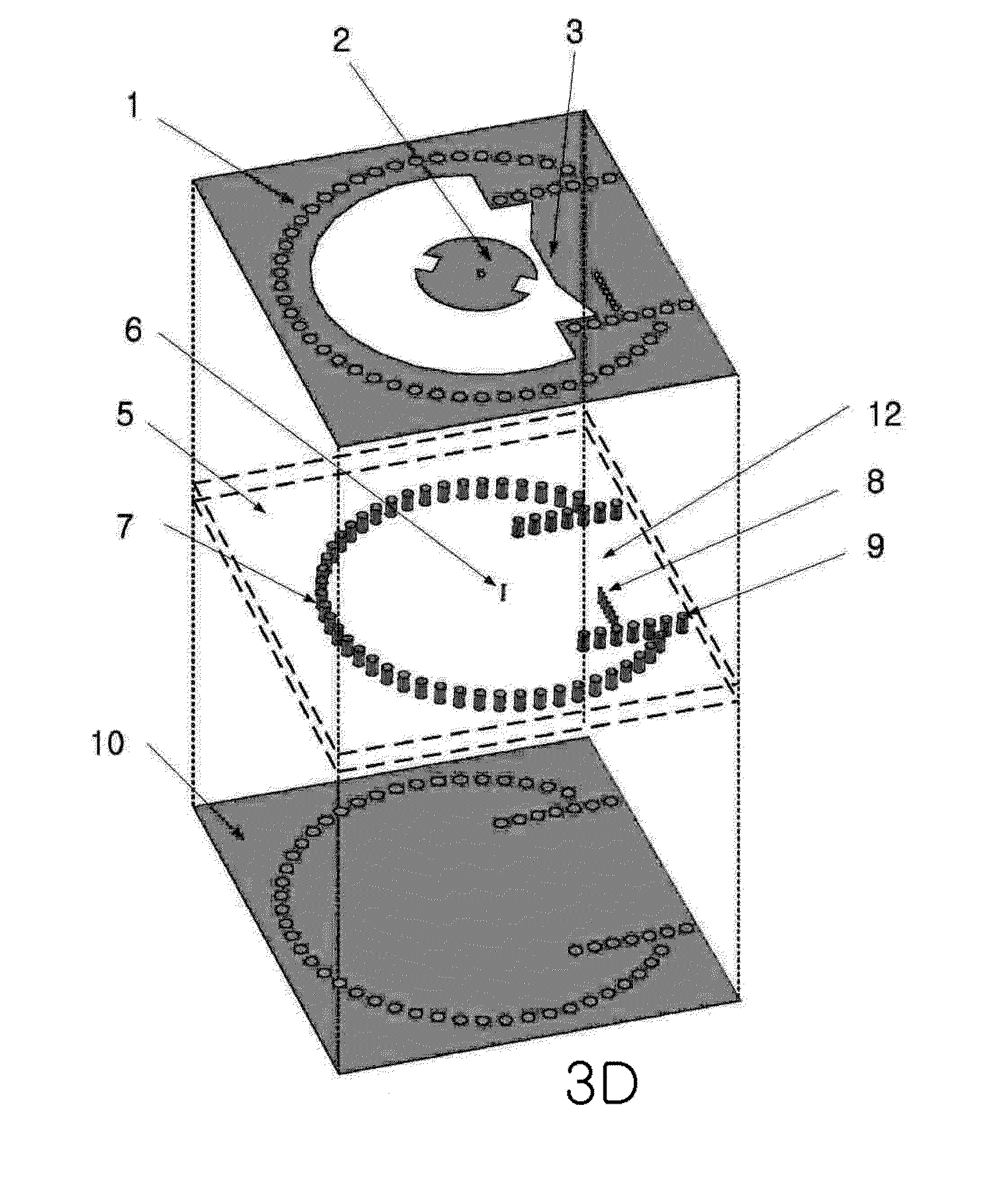
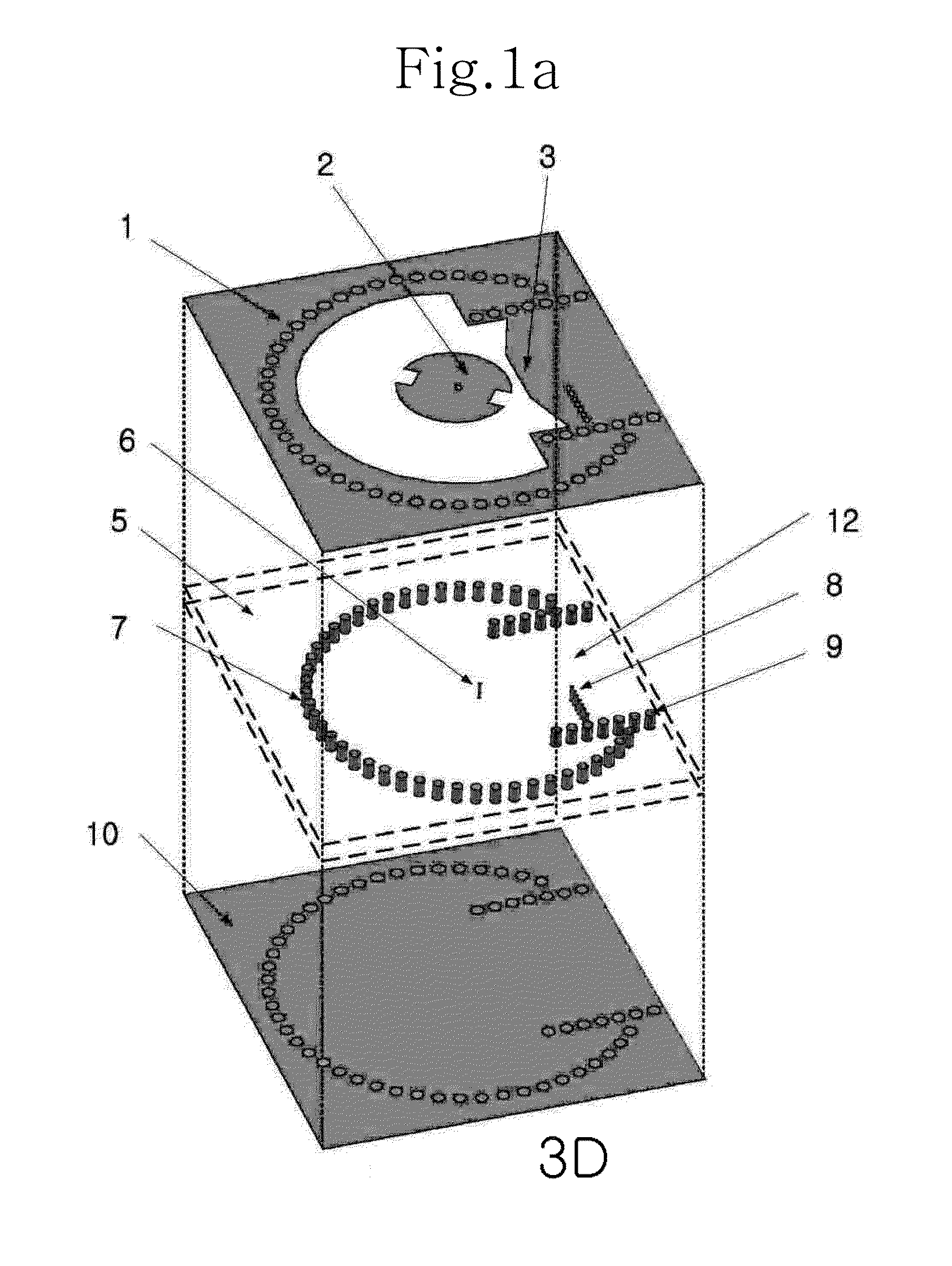
[0042]FIG. 1A is a 3D exploded perspective view of an antenna according to the present invention. In particular, the illustrated antenna is a circularly polarized antenna for satellite communication, which is of an X-band operating dielectric substrate integrated cylindrical cavity type.

[0043]As illustrated in FIG. 1A, the circularly polarized antenna for sa...


PUM


Abstract

A circularly polarized antenna includes a dielectric substrate having a first via array in the form of a cylindrical cavity, a micro-strip circular patch antenna located at the center of the cylindrical cavity and formed on the dielectric substrate to radiate a signal, and a rectangular dielectrically loaded waveguide having a second via array and serving to feed the signal to the micro-strip circular patch antenna. Accordingly, the circularly polarized antenna prevents impedance mismatch between the micro-strip antenna and the dielectrically loaded waveguide and broadens an impedance bandwidth thereof.

Description

BACKGROUND OF THE INVENTION[0001]1. Field of the Invention[0002]The present invention relates to a circularly polarized antenna for satellite communication, and more particularly, to a circularly polarized antenna for satellite communication, which adopts a feed method using a dielectrically loaded waveguide and realizes a small antenna using a waveguide capable of being integrated on a single dielectric substrate, thereby minimizing feed loss in a high frequency band of satellite communication and broadening an impedance bandwidth via integration of an impedance matching network and circular polarization.[0003]2. Description of the Related Art[0004]Antennas devised to be mounted and used in satellites have needs for stabilized gain, circular polarization and bandwidths. In addition, these antennas must have strong heat resistance to exhibit stabilized characteristics even under space environments and must be designed firmly and lightly to prevent physical damage thereto even by vib...

Claims


Application Information

Patent Timeline
IPC IPC(8): H01Q9/04H01Q1/50
CPCH01Q9/045H01Q9/0407H01Q1/38H01Q9/0428H01Q9/0442H01Q13/106
Inventor LEE, JAE WOOKKIM, DONG YEONSEO, TAE YOONAHN, SUNG HWAN
Owner IND UNIV COOP FOUND KOAEA AEROSPACE UNIV
Why Eureka
Try Eureka