Recording medium, playback device, and integrated circuit

a playback device and integrated circuit technology, applied in the field of 3d video playback and 2d video, can solve the problems of increasing costs, and achieve the effect of suppressing the amount of duplicate data stored in different extents

Active Publication Date: 2010-09-30
PANASONIC CORP
View PDF30 Cites 79 Cited by
  • Summary
  • Abstract
  • Description
  • Claims
  • Application Information

AI Technical Summary

Benefits of technology

[0020]According to the recording medium pertaining to the present invention, an area on which a data block group referred to immediately before a long jump is stored is different between a monoscopic playback file and a streoscopic playback file, and accordingly, a playback path is divided into a playback path of 2D video and a playback path of 3D video immediately before the long jump. Consequently, the size of an extent referred to immediately before the long jump can be designed independently for monoscopic playback and for stereoscopic playback, thereby allowing a reduction in a buffer amount to be secured during stereoscopic playback.
[0021]Furthermore, in the playback path of 2D video, because the 2D data block referred to immediately before the long jump succeeds the common data block group shared by two types of files, the common data block group can be used as a part of an extent of the monoscopic playback file referred to immediately before the long jump. On the other hand, among extents referred to immediately before the long jump in the monoscopic playback file, the above-described common data block group is also used as an extent of the stereoscopic playback file, and thus, an increase in the amount of duplicate data which is stored in different extents can be suppressed.
[0022]Also, because the contents which are identical between the monoscopic playback file and the stereoscopic playback file are arranged as a group, data for multiple connection such as 1 playback path connecting to n playback paths after a long jump can be generated.

Problems solved by technology

If the 2D playback device cannot play back the 3D video stored on the optical disc, as 2D video, the same contents need to be manufactured in two types of discs, i.e. 3D discs and 2D discs, leading to a cost increase.

Method used


Image

  • Recording medium, playback device, and integrated circuit
  • Recording medium, playback device, and integrated circuit
  • Recording medium, playback device, and integrated circuit

Examples


first embodiment

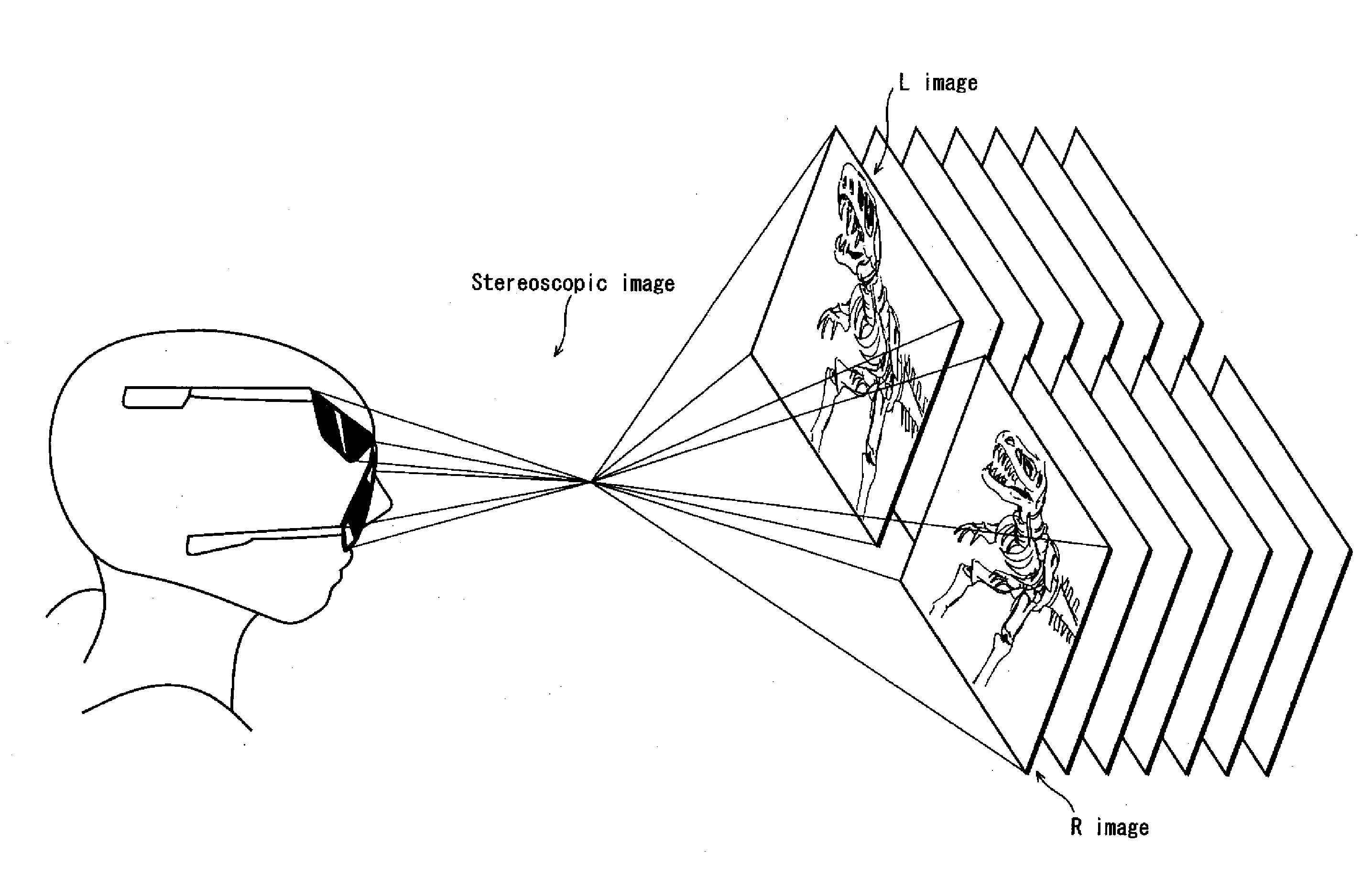
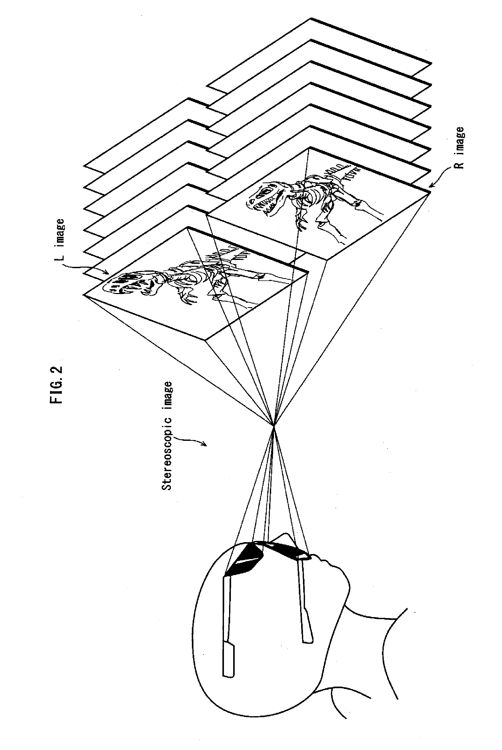
[0130]First, a brief description is given of the principle of the stereoscopic view.

[0131]In general, due to the difference in position between the right eye and the left eye, there is a little difference between an image seen by the right eye and an image seen by the left eye. It is this difference that enables the human beings to recognize the image they see in three dimensions. The stereoscopic display is realized by using the parallax of human beings, so that a monoscopic image looks as if it is three-dimensional.

[0132]More specifically, there is a difference between the image seen by the right eye and the image seen by the left eye, the difference corresponding to parallax of human beings. The stereoscopic display is realized by displaying the two types of images alternately at regular short time intervals.

[0133]The “short time interval” may be a time period that is short enough to provide human beings, by the alternate displays, an illusion that they are seeing a three-dimensi...

second embodiment

[0921]In the first embodiment, as shown in FIG. 54, data is input to the system target decoder by using two buffers, i.e., the first read buffer 4921 and the second read buffer 4922. However, in the second embodiment, a structure that realizes 3D video playback by using only one buffer will be explained.

[0922]Specifically, as shown in FIG. 89, data is input to the system target decoder 3703 from only the read buffer 3707, and, as shown in FIG. 90, the data may be input to the source depacketizer (1) 4111 and the source depacktizer (2) 4112 from the read buffer 3707.

[0923]This structure can cause a size of the read buffer required for the 2D / 3D playback apparatus to play back 3D images to be reduced.

[0924]The upper level of FIG. 91 shows a transition of data amounts of data accumulated in the first read buffer 4921 during 3D playback when using two buffers, i.e., the first read buffer 4921 and the second read buffer 4922.

[0925]The middle level of FIG. 91 shows a transition of data am...

third embodiment

[0933]The following describes, as the second embodiment of the present invention, a recording device and a recording method for recording the recording medium of the first embodiment of the present invention.

[0934]The recording device described here is called an authoring device. The authoring device, generally located at a creation studio that creates movie contents to be distributed, is used by authoring staff. First, in accordance with operations by the authoring staff, the recording apparatus converts movie content into a digital stream that is compression encoded in accordance with an MPEG specification, i.e. into an AV stream file. Next, the recording device generates a scenario, which is information defining how each title included in the movie content is to be played back. Specifically, the scenario includes the above-described dynamic scenario information and static scenario information. Then, the recording device generates a volume image or an update kit for a BD-ROM disc ...


PUM


Abstract

Provided is a recording medium that enables seamless connection between preceding playitems which are stream data arranged prior to a position where a long jump occurs, such as a layer boundary, and succeeding playitems which are stream data arranged subsequent to the position where the long jump occurs. A block exclusively for 2D playback Ln2D is arranged succeeding a 3D extent block in which a depth map data block, a right-view data block, and a left-view data block are arranged in an interleaved manner. A 3D extent block including a block exclusively for 3D playback L3SS is arranged between the block exclusively for 2D playback and a long jump point LB. The block exclusively for 2D playback and the block exclusively for 3D playback are identical in content.

Description

BACKGROUND OF THE INVENTION[0001](1) Field of the Invention[0002]The present invention belongs to a technical field of a playback technology for 3D video and 2D video.[0003]The present invention relates a playback technology for stereoscopic video, and in particular, to the allocation of video data on a recording medium.[0004](2) Description of the Related Art[0005]In recent years, along with an increase in the number of 3D movie works, there is an increasing demand for storing 3D video in optical discs while maintaining the 3D video at high image quality, in order to supply these movie works for home use.[0006]When storing 3D video on an optical disc, the disc requires playback compatibility with a playback device that can playback only an optical disc having stored 2D video (hereinafter, referred to as “2D playback device”). If the 2D playback device cannot play back the 3D video stored on the optical disc, as 2D video, the same contents need to be manufactured in two types of dis...

Claims


Application Information

Patent Timeline
Patent Type & Authority Applications(United States)
IPC IPC(8): H04N13/04
CPCG11B27/105H04N19/597H04N5/765H04N5/775H04N5/85H04N9/7921H04N9/8042H04N9/8063H04N9/8205H04N9/8216H04N9/8227H04N9/8244H04N13/0048H04N13/0055H04N13/0059H04N13/0066H04N13/007H04N13/0404H04N13/0434H04N13/0438H04N13/0456G11B2020/10814G11B2020/10916G11B2020/10925G11B2220/2541H04N13/161H04N13/178H04N13/183H04N13/189H04N13/194H04N13/305H04N13/337H04N13/341H04N13/361
Inventor SASAKI, TAIJIYAHATA, HIROSHIIKEDA, WATARUOGAWA, TOMOKI
Owner PANASONIC CORP
Why Eureka
Try Eureka