Translating Hinge

a technology of hinges and hinge plates, applied in the field of hinges, can solve the problems of limiting the locations/applications in which the hinge can be used, the hinge is relatively difficult to spring load, and the assembly is relatively bulky, so as to reduce the chance of damage to either assembly, improve the serviceability of both assemblies, and improve the reliability of the system

Active Publication Date: 2010-09-30
RAYTHEON CO
View PDF71 Cites 13 Cited by
  • Summary
  • Abstract
  • Description
  • Claims
  • Application Information

AI Technical Summary

Benefits of technology

[0017]By coupling the two cold plates via a translating hinge the cold plates can be separated thereby providing access to the electronics. Thus, coupling the cold plates via a translating hinge is beneficial because the translating hinge captivates both assemblies (i.e. both cold plates with the associated electronics) thus improving serviceability of both assemblies.
[0018]Furthermore, since the two heat sinks are coupled via the translating hinge, it is not necessary to completely separate the two heat sinks for servicing either the heat sinks or the electronics. Since neither heat sink is loose during service, this reduces the chance of damage to either assembly while one (or both) of the assemblies is being serviced. Coupling the heat sinks via translating hinges can also eliminate the need for a coolant quick disconnects that would otherwise be required to separate the cold plates. Fewer quick disconnect couplings means fewer leaks and a more robust, reliable system. Furthermore, the translating hinge described herein allows electrical interconnections between the two assemblies to remain intact during servicing. This reduces the possibility of damage to connectors (e.g. due to disconnecting and reconnecting electrical connectors) and allows access to the heat sinks and electronics and testing thereof to be performed in an easily accessible configuration.
[0019]By allowing for more than two layers of components to be hinged together and independently accessible, the translating hinge described herein also provides a framework for future growth of RF systems utilizing panel array antenna architectures. For example, a stack of three or more cold plates could be coupled via translating hinges. Assemblies other than cold plates or heat sink assemblies could also be stacked. For example, multiple electronics modules which do not require a heat sink could be stacked. Or combinations of cold plates, heat sinks and / or electronics modules could be coupled via translating hinges. Thus, the hinge itself is scalable to operate with objects of different sizes and shapes while at the same time providing system scalability.
[0020]The translating hinge described herein thus preferably incorporates at least one or more of the following characteristics: (1) the hinge axis of rotation is within a predefined envelope of an LRU which allows serviceability of the LRU while assembled into a tightly packed structure (e.g. a RF system having a panel architecture); (2) having the axis of rotation within the LRU envelope requires translation before rotation; (3) the object undergoing the translation movement is stable in a translated position; (4) the two objects coupled by the translating hinge can be precisely aligned to each other to allow accurate blind mating to occur (e.g. blind mating of electrical interconnects and / or EMI gaskets between the two objects).

Problems solved by technology

Some of the drawbacks of the four bar linkage techniques are: (1) the resulting hinge does not translate in a direction which is perpendicular to a mating surface; (2) the resulting hinge has many moving parts; (3) the resulting hinge is a relatively bulky assembly and thus limits the locations / applications in which the hinge can be used.
Some of the drawbacks of the slotted hinge techniques are: (1) rotation can occur before translation is complete (which could be undesirable in some applications which require translation to be complete prior to rotation); (2) the resulting hinge is relatively difficult to spring load at the translated position; and (3) tight tolerances are relatively difficult to achieve due to the precision with which a slot can be provided in the hinge structure since in general, fabrication of slots is typically accomplished by interpolating an outer profile of the slot with an end mill of a smaller diameter than the slot width.
Slots provided using this technique struggle to achieve tolerances greater than ±0.002 in. especially when the ratio of slot depth to end mill diameter exceeds 5 to 1.

Method used


Image

  • Translating Hinge
  • Translating Hinge
  • Translating Hinge

Examples


Embodiment Construction

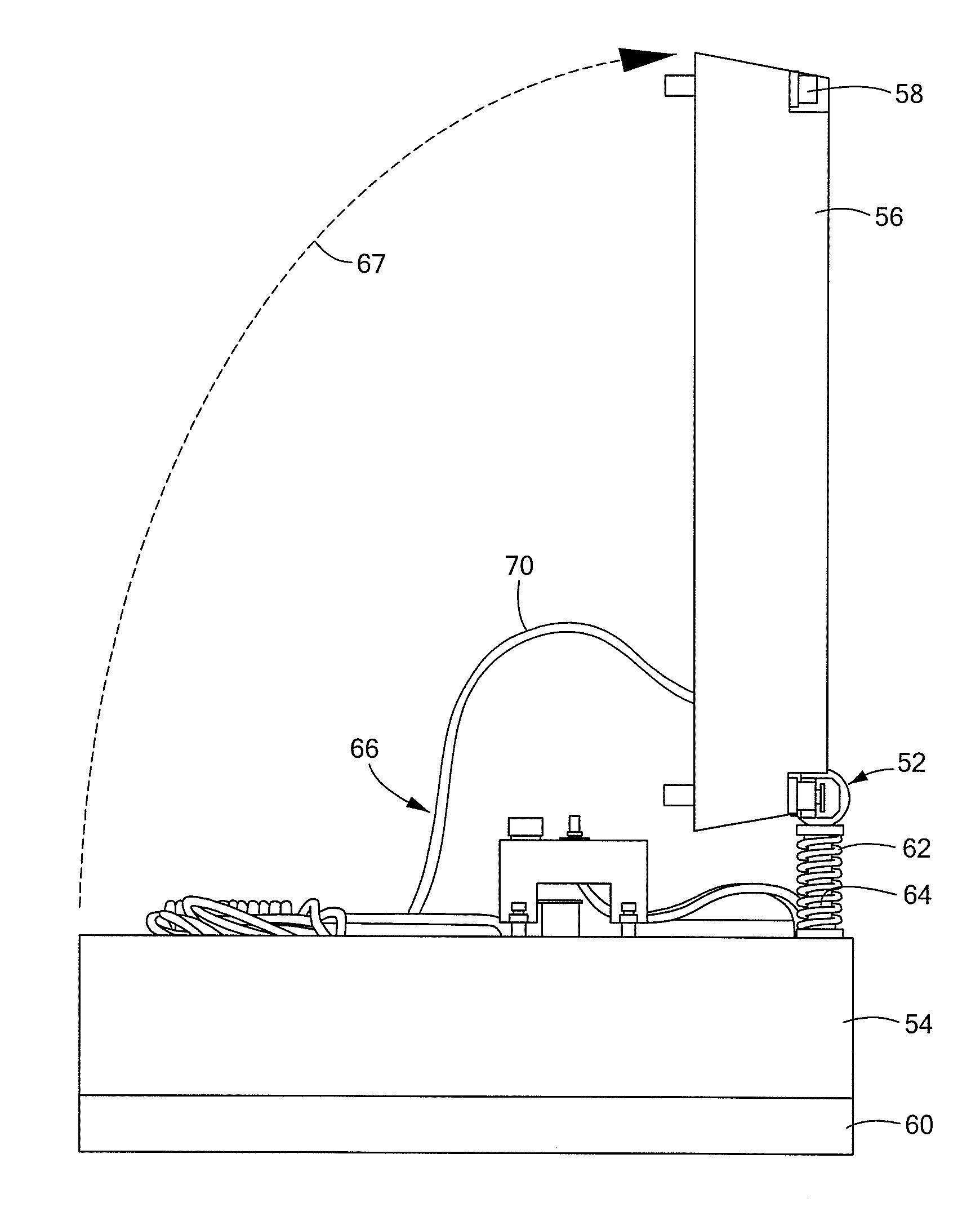
[0032]Described herein is a translating hinge which can be used to couple two objects. Before describing a translating hinge, it should be appreciated that reference is sometimes made herein to a translating hinge being used in a radio frequency (RF) transmit / receive system and in particular in a radar system having a so-called panel architecture. It should also be appreciated, however, that references to such radar systems are made only for the purpose of promoting clarity in the description and drawings with respect to the concepts being described and claimed and such references are not intended to be, and should not be, construed as limiting.

[0033]It is fully appreciated that the translating hinge concepts described herein find use in a wide variety of applications including both commercial and military applications. The translating hinge concepts described herein may find particular use in any application in which it is desired to include a hinge which provides both a translatio...


PUM


Abstract

A translating hinge includes a translation element which provides translational movement between two objects coupled by the translating hinge and a rotating assembly coupled to the translation element.

Description

RELATED APPLICATIONS[0001]This application claims the benefit of U.S. Provisional Application No. 61 / 162,748 filed on Mar. 24, 2009 under 35 U.S.C. §119(e) which application is hereby incorporated herein by reference in its entirety.FIELD OF THE INVENTION[0002]The structures and techniques described herein relate to bearings and more particularly to hinges.BACKGROUND OF THE INVENTION[0003]As is known in the art, a bearing is a device which allows constrained relative motion, typically rotation or linear movement, between two parts or objects. Bearings may be classified broadly according to the motions they allow and according to their principle of operation as well as by the directions of applied loads they can handle.[0004]A hinge is a type of bearing that connects two objects, typically allowing only a limited angle of rotation between the objects. Two objects connected by an ideal hinge rotate relative to each other about a fixed axis of rotation (the geometrical axis of the hing...

Claims


Application Information

Patent Timeline
Patent Type & Authority Applications(United States)
IPC IPC(8): H05K7/20E05D5/10E05D7/04
CPCE05D3/022H01Q1/02H01Q21/0025H01Q21/061Y10T16/557Y10T16/5353Y10T16/53834Y10T16/532Y10T16/5327Y10T16/5324Y10T16/53257H05K7/16
Inventor PAQUETTE, JEFFREYCHEYNE, SCOTT R.
Owner RAYTHEON CO
Why Eureka
Try Eureka