
System and method for reading micro-holograms with reduced error rates

a micro-hologram and error rate technology, applied in the field of bitwise optical data storage techniques, can solve problems such as interference, and achieve the effect of better estimation

Active Publication Date: 2010-09-30
GENERAL ELECTRIC CO
View PDF2 Cites 0 Cited by
  • Summary
  • Abstract
  • Description
  • Claims
  • Application Information

AI Technical Summary

Benefits of technology

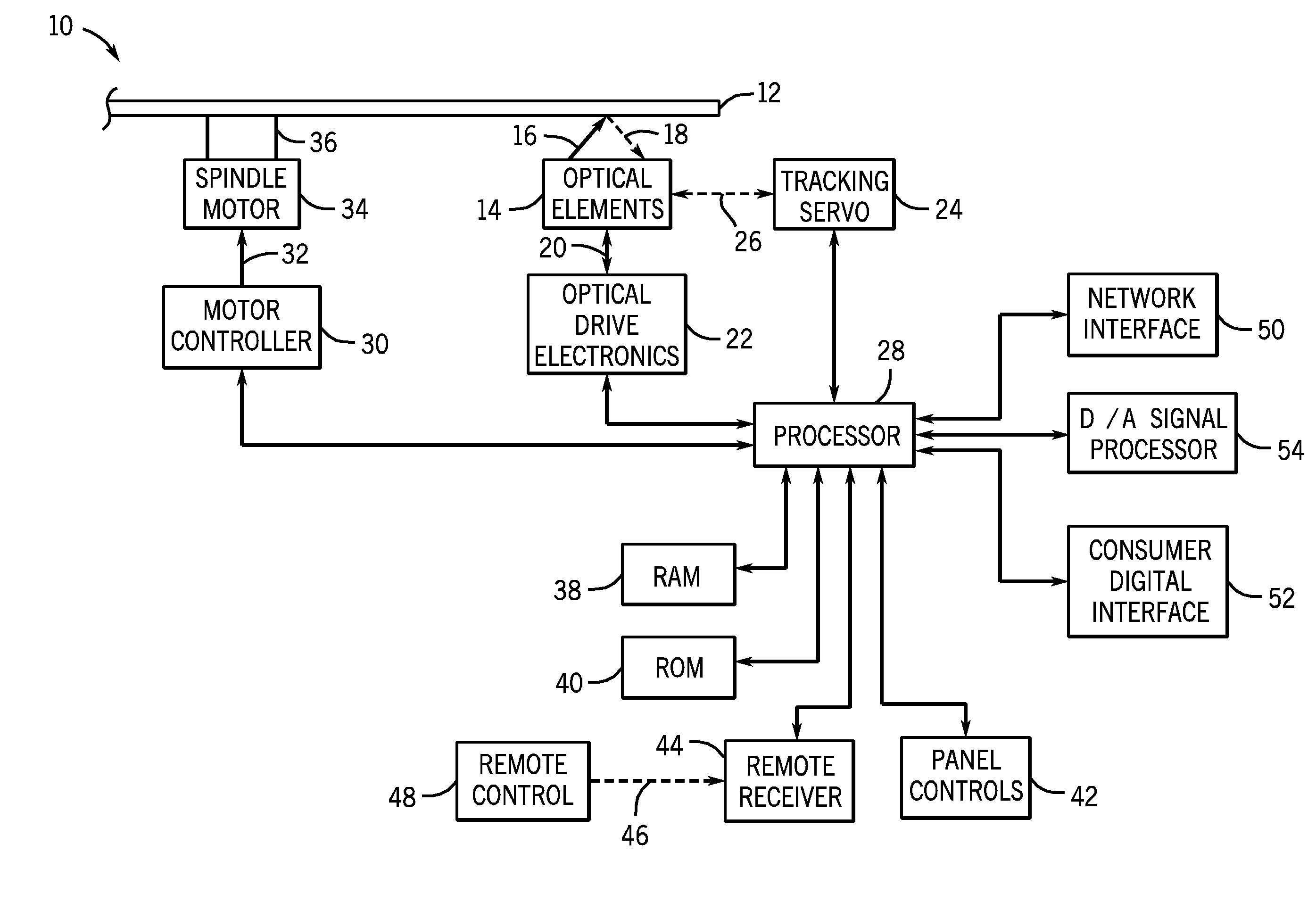
[0008]An embodiment of the present techniques provides a method of reading an optical data disc. The method includes directing a read beam towards a data bit of interest to generate an optical return, which includes light from the read beam scattered by the data bit of interest. The method further includes detecting the optical return from multiple positions and analyzing the optical return from each of the multiple positions to obtain an improved estimate. The improved estimate enables a better estimation of the state of the data bit of interest than the optical returns from each of the multiple positions.
[0010]A further embodiment provides a method of reducing error in reading a data bit of interest on an optical disc. The method comprises positioning the detector to obtain a data reading from the data bit of interest, based on one or more parameters of either the optical data disc or the system for reading the optical data disc. The method further comprises detecting multiple data readings, where a data reading is detected from each of the multiple detector positions. Further, an improved estimate is obtained based on the multiple data readings.

Problems solved by technology

Although holographic storage systems may provide much higher storage capacities than prior optical systems, as is the case for all optical storage media, they may be vulnerable to interferences.
For example, interferences may result from the closely spaced bits in adjacent tracks and layers.

Method used


Image

  • System and method for reading micro-holograms with reduced error rates
  • System and method for reading micro-holograms with reduced error rates
  • System and method for reading micro-holograms with reduced error rates

Examples


Embodiment Construction

[0020]One or more embodiments of the present techniques will be described below. In an effort to provide a concise description of these embodiments, not all features of an actual implementation are described in the specification. It should be appreciated that in the development of any such actual implementation, as in any engineering or design project, numerous implementation-specific decisions must be made to achieve the developers' specific goals, such as compliance with system-related and business-related constraints, which may vary from one implementation to another. Moreover, it should be appreciated that such a development effort might be complex and time consuming, but would nevertheless be a routine undertaking of design, fabrication, and manufacture for one of ordinary skill having the benefit of this disclosure.

[0021]Bit-wise holographic data storage systems typically use a focused laser as a read beam to read data bits, represented by the presence or absence of micro-holo...


PUM

PropertyMeasurementUnit
threshold valueaaaaaaaaaa
sizeaaaaaaaaaa
shapeaaaaaaaaaa

Abstract

The present techniques provide methods and systems reading a data bit of interest on an optical data disc with a reduced error rate. The data bit estimation may be improved by reducing deterministic noise resulting from an optical reader system and / or the optical data disc. The reader may adjust the position of a detector to detect light scattered from the disc based on parameters of known noise sources. In one embodiment, the detector may be moved vertically in relation to the data bit of interest on the optical disc. In another embodiment, more than one detector may be used to detect light scattered from a data bit of interest. In embodiments, the positioning of the detector(s) may be based on system or disc parameters, and the detected scatterings may provide a data reading, improved for an optical return from a present micro-hologram.

Description

BACKGROUND[0001]The present techniques relate generally to bit-wise optical data storage techniques. More specifically, the techniques relate to methods and systems for reducing error rates while reading bits on optical discs.[0002]As computing power has advanced, computing technology has entered new application areas, such as consumer video, data archiving, document storage, imaging, and movie production, among others. These applications have provided a continuing push to develop data storage techniques that have increased storage capacity. Further, increases in storage capacity have both enabled and promoted the development of technologies that have gone far beyond the initial expectations of the developers, such as gaming, among others.[0003]The progressively higher storage capacities for optical storage systems provide a good example of the developments in data storage technologies. The compact disc, or CD, format, developed in the early 1980s, has a capacity of around 650-700 M...

Claims


Application Information

Patent Timeline
Patent Type & Authority Applications(United States)
IPC IPC(8): G11B20/18
CPCG11B7/005G11B7/0065G11B2220/2504G11B20/18G11B2007/0009G11B7/013
Inventor HERSHEY, JOHN ERIKWELLES, KENNETH BRAKELEYROSS, JOHN ANDERSON FERGUSGRAF, JOHN FREDERICKLAWRENCE, BRIAN LEESHI, XIAOLEIREN, ZHIYUANOSTROVERKHOV, VICTOR PETROVICH
Owner GENERAL ELECTRIC CO
Learn More