Stent

Active Publication Date: 2010-09-30
CR BARD INC
View PDF99 Cites 36 Cited by
  • Summary
  • Abstract
  • Description
  • Claims
  • Application Information

AI Technical Summary

Benefits of technology

[0008]According to the present invention, a stent as identified above is improved by arranging that, for

Problems solved by technology

Such a change of shape necessitates the occurrence of strain within the matrix.
However, building a stent annulus with convoluted or serpentine

Method used


Image

  • Stent
  • Stent
  • Stent

Examples


Embodiment Construction

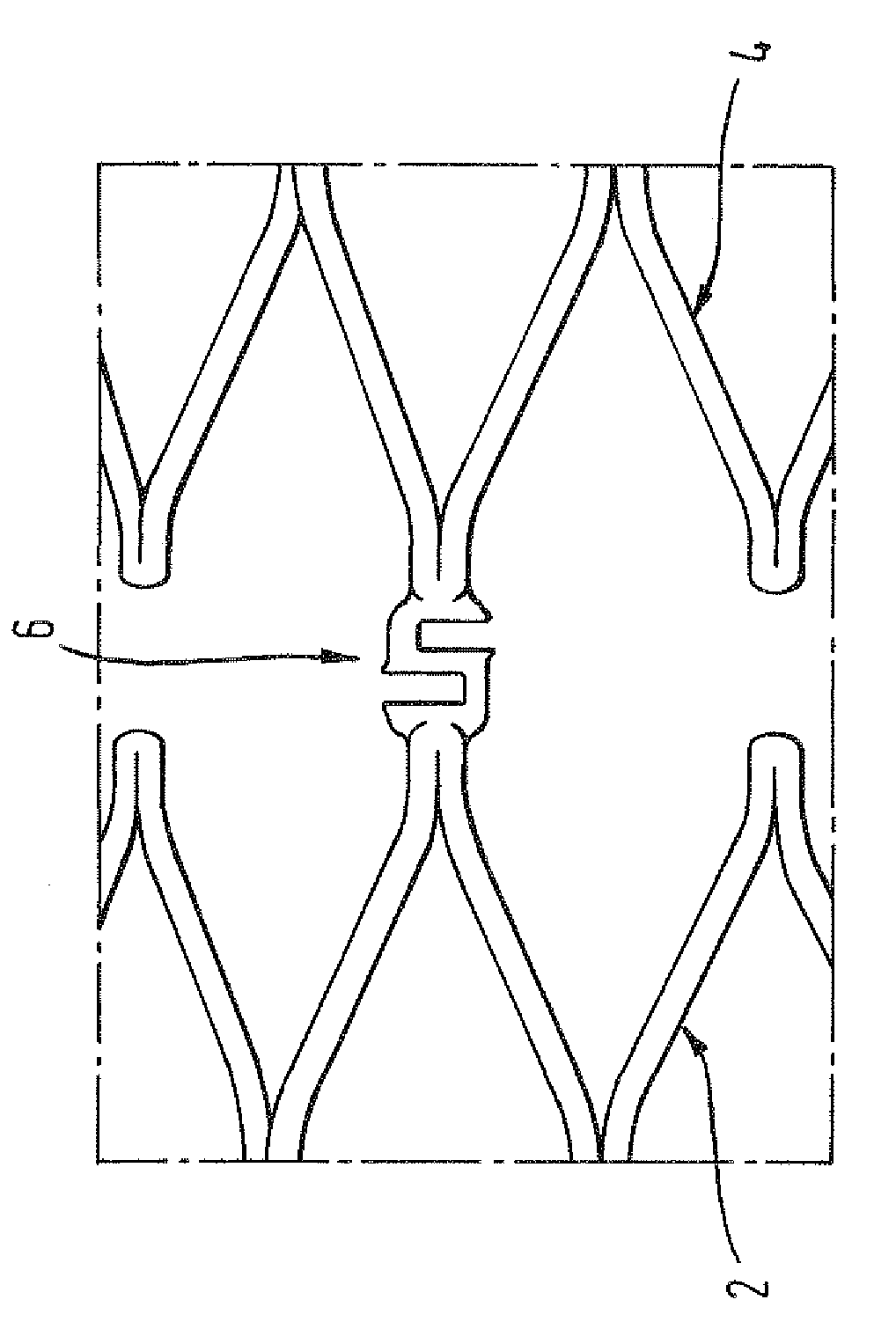
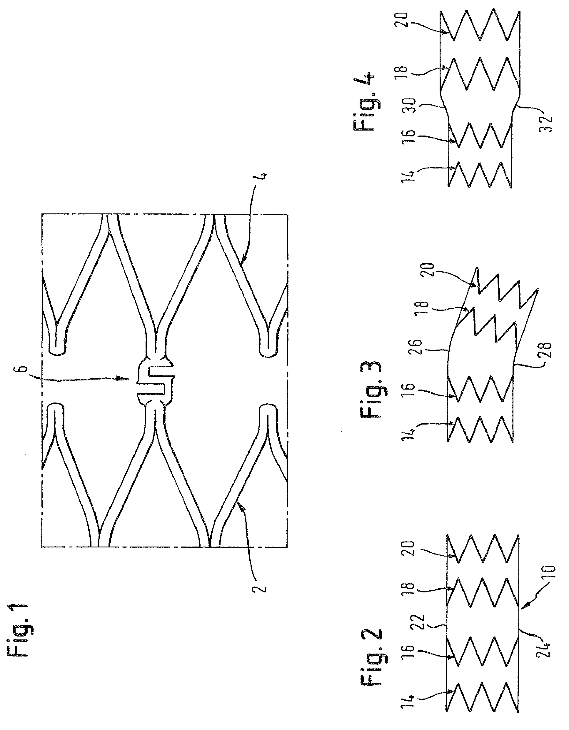
[0020]Looking first at FIG. 1, the skilled reader will recognise portions of two adjacent zig-zag stenting rings 2, 4 and a single connector 6 of those two adjacent rings, central in the drawing Figure. That connector 6 shows a serpentine form, resembling the letter “S” lying on its side and with the base of the letter S contiguous with one of the two zig-zag stenting rings 2, 4 and the top of the letter S contiguous with the other of the two stenting rings. Self-evidently, the serpentine form of the connector 6 provides the stent matrix with capacity to undergo strain, somewhat additional to the capacity it would have if the serpentine connector 6 were to be replaced by a short straight link connecting the two zig-zag stenting rings 2, 4.

[0021]Turning to FIG. 2, we see diagrammatically a stent 10 composed of four zig-zag stenting rings 14, 16, 18 and 20 like the zig-zag rings shown in FIG. 1. The longitudinal straight lines 22 and 24 indicate the general form of the annulus of the ...


PUM

PropertyMeasurementUnit
Thicknessaaaaaaaaaa
Lengthaaaaaaaaaa
Shape memory effectaaaaaaaaaa

Abstract

A radially expansible annular stent is disclosed. The stent comprises a plurality of stenting turns around a lumen centred on a longitudinal axis. Adjacent turns of the stent are joined by connector struts. The stent annulus has a wall thickness related to the material from which it is formed. The radial thickness of the connector struts is smaller than that of the stent annulus. A method of making such a stent is also disclosed. The method includes cutting the connector struts from a tubular workpiece with a laser beam. The laser beam is aimed so as to be offset from a longitudinal axis of the workpiece to provide the reduced radial thickness of the connector struts.

Description

FIELD OF THE INVENTION[0001]This invention relates to a radially-expansible annular stent comprising a plurality of stenting turns around a lumen centered on a longitudinal axis, with adjacent turns being joined by connector struts, the stent annulus having a wall thickness that is related to the material of which it is formed.BACKGROUND ART[0002]In the field of radially expansible annular stents that are called upon, in use, to resist a radially inwardly directed force from surrounding bodily tissue, in order to maintain a bodily lumen patent, there is a contradictory design requirement. On the one hand, the stent must be strong enough to keep the lumen patent. On the other hand, the stent prosthesis must be flexible enough to accommodate movement of surrounding bodily tissue.[0003]There are two archetypal stent forms. One of them has a stack of closed loop stenting rings, the length direction of the stent being along the length of the longitudinal axis of the annulus of the stent....

Claims


Application Information

Patent Timeline
IPC IPC(8): A61F2/82A61F2/915
CPCA61F2/915A61F2002/91541A61F2230/0054A61F2250/0036A61F2002/91558A61F2230/0069A61F2240/002B23K2103/42A61F2240/001A61F2250/0039A61F2/86B23K26/38A61F2/89B23K26/402
Inventor WACK, THILOHAAS, THOMAS
Owner CR BARD INC
Why Eureka
Try Eureka