System and method for rendering visible features of a target location on a synthetic flight display

a technology of synthetic flight display and target location, applied in the field of avionics systems, can solve the problems of cluttered and user-unfriendly synthetic flight display, unnecessary and distracting display of additional features,

Active Publication Date: 2010-09-30
HONEYWELL INT INC
View PDF13 Cites 93 Cited by
  • Summary
  • Abstract
  • Description
  • Claims
  • Application Information

AI Technical Summary

Benefits of technology

[0008]This summary is provided to introduce a selection of concepts in a simplified form that are further described below in the detailed description. This summary is not in...

Problems solved by technology

Displaying additional features (such as other runways, ground markings, or landscape features) may be unnecessary and...

Method used


Image

  • System and method for rendering visible features of a target location on a synthetic flight display
  • System and method for rendering visible features of a target location on a synthetic flight display
  • System and method for rendering visible features of a target location on a synthetic flight display

Examples


Embodiment Construction

[0013]The following detailed description is merely illustrative in nature and is not intended to limit the embodiments of the subject matter or the application and uses of such embodiments. As used herein, the word “exemplary” means “serving as an example, instance, or illustration.” Any implementation described herein as exemplary is not necessarily to be construed as preferred or advantageous over other implementations. Furthermore, there is no intention to be bound by any expressed or implied theory presented in the preceding technical field, background, brief summary or the following detailed description.

[0014]Techniques and technologies may be described herein in terms of functional and / or logical block components, and with reference to symbolic representations of operations, processing tasks, and functions that may be performed by various computing components or devices. Such operations, tasks, and functions are sometimes referred to as being computer-executed, computerized, s...


PUM


Abstract

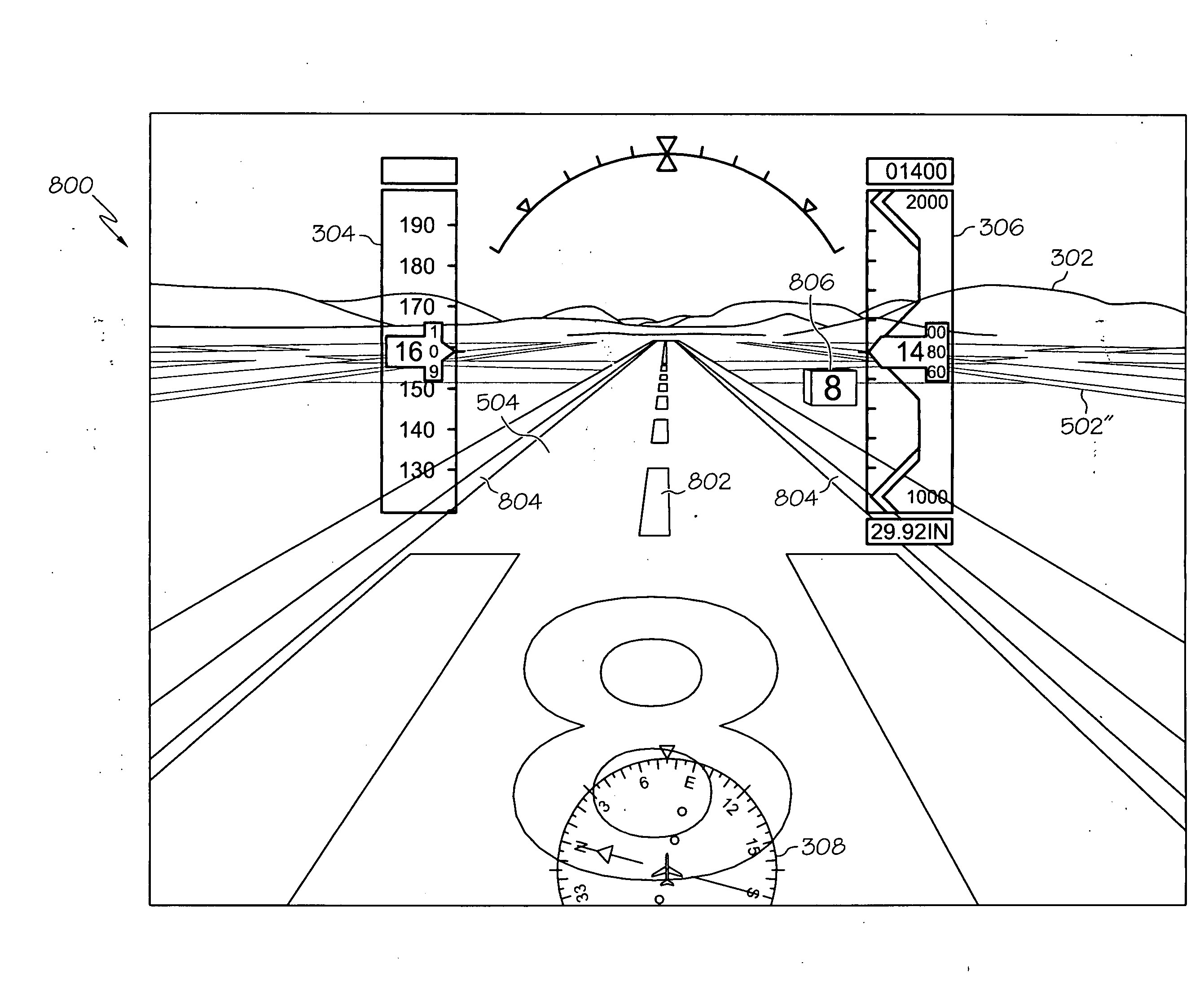
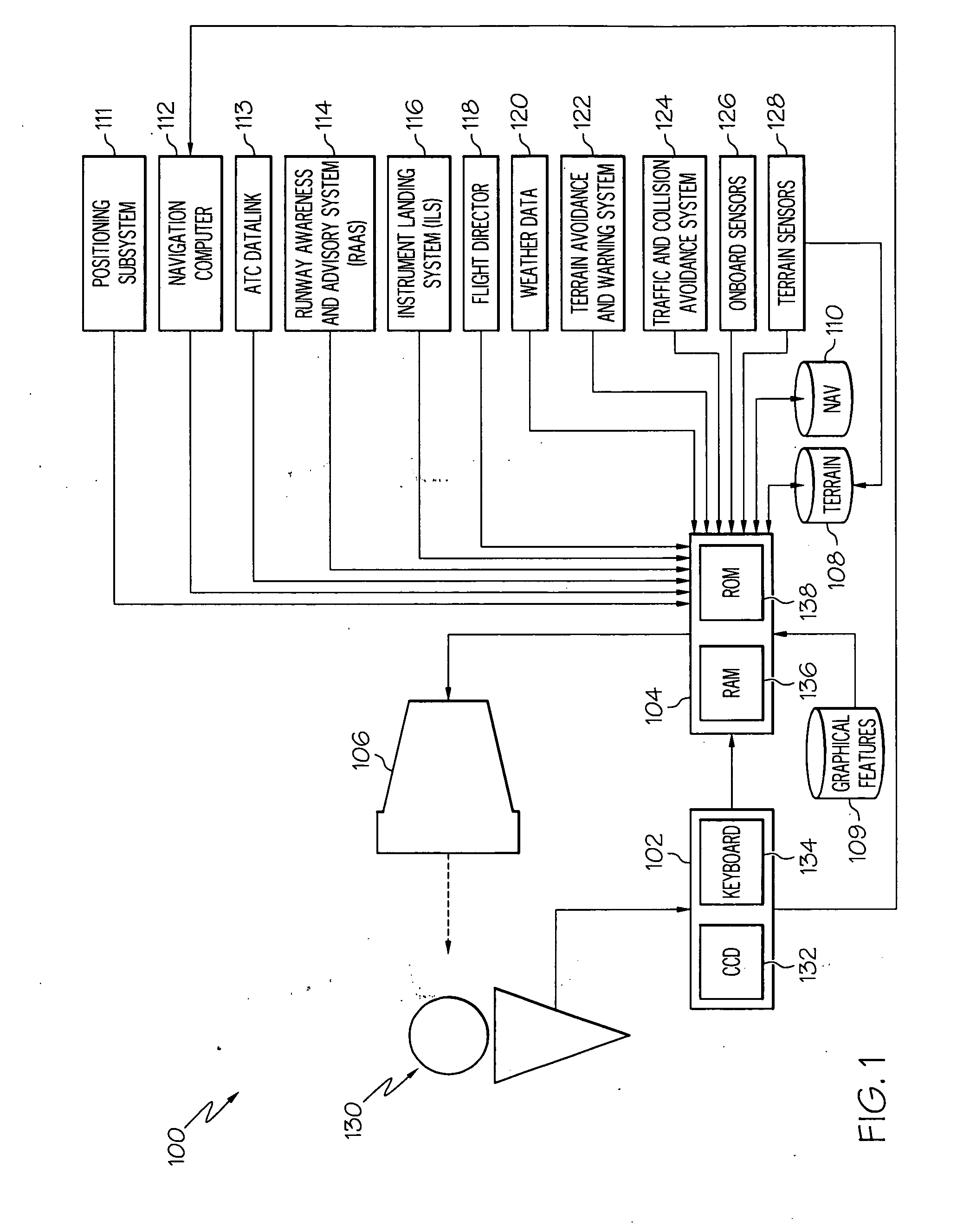
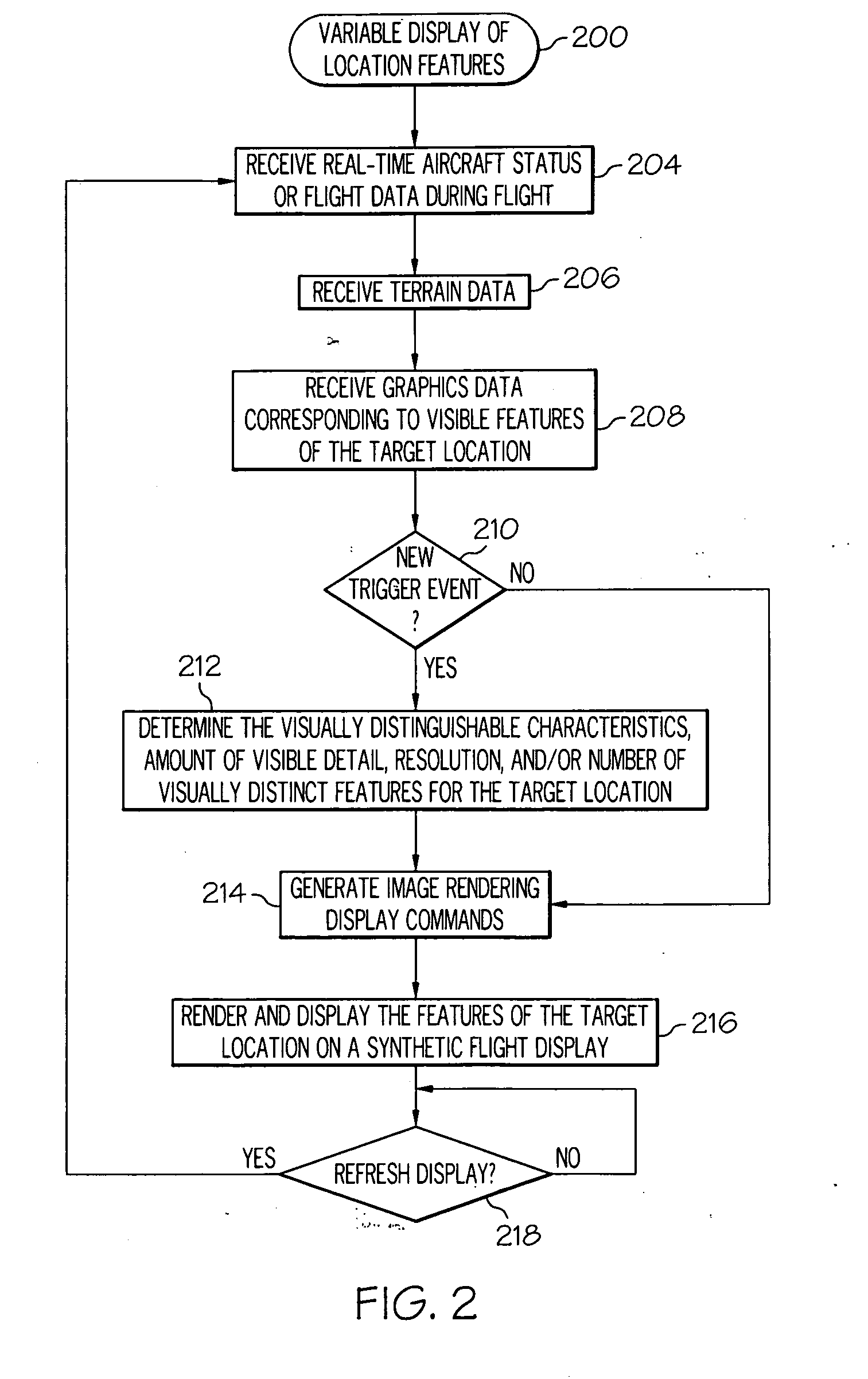
A flight deck display system for an aircraft or other vehicle includes a first data source of visual feature data that is indicative of visual features of a location of interest, a second data source of flight data for the aircraft, a processor architecture, and a display element. The processor architecture is operatively coupled to the first data source and to the second data source, and it is configured to process the visual feature data, process the flight data, and, based upon the visual feature data and the flight data, generate image rendering display commands. The display element receives the image rendering display commands and, in response thereto, renders a dynamic graphical representation of the location of interest using the visual feature data. The dynamic graphical representation of the location conveys an amount of visible detail that varies as a function of the flight data.

Description

TECHNICAL FIELD[0001]Embodiments of the subject matter described herein relate generally to avionics systems such as flight display systems. More particularly, embodiments of the subject matter relate to a flight deck display system that generates a synthetic flight display that includes a graphical representation of a location of interest, such as an airport, using variable display characteristics.BACKGROUND[0002]Modern flight deck displays for vehicles (such as aircraft or spacecraft) display a considerable amount of information, such as vehicle position, speed, altitude, attitude, navigation, target, and terrain information. In the case of an aircraft, most modern displays additionally display a flight plan from different views, either a lateral view, a vertical view, or a perspective view, which can be displayed individually or simultaneously on the same display.[0003]The lateral view, generally known as a lateral map display, is basically a top-view of the flight plan, and may ...

Claims


Application Information

Patent Timeline
IPC IPC(8): G01C23/00
CPCG01C23/005G08G5/025G08G5/0065G08G5/0021
Inventor NICHOLS, TROYFEYEREISEN, THEA L.HE, GANGPEPITONE, DAVE
Owner HONEYWELL INT INC
Why Eureka
Try Eureka