Battery measuring device, battery control system and vehicle

a technology for controlling systems and battery devices, applied in the direction of battery/fuel cell control arrangements, process and machine control, instruments, etc., can solve the problems of inability to function, difficult to measure performance, and large amount of electricity required

Active Publication Date: 2010-09-30
KK TOSHIBA
View PDF1 Cites 47 Cited by
  • Summary
  • Abstract
  • Description
  • Claims
  • Application Information

AI Technical Summary

Benefits of technology

[0012]Rc1=DC pulse resistance value of first discharging period−AC resistance value, and which estimates at least an internal resistance of the secondary battery using the temperature T1, electric resistance Re1 and reaction resistance Rc1.
[0013]According to another aspect of the present invention, it is provided that a battery control system includes: the battery measuring device; and a deterioration determining unit which determines a deterioration condition of the secondary battery based on the reaction resistance Rc1.
[0014]According to another aspect of the present invention, it is provided that a vehicle includes the battery control system, and operates by power supplied from the secondary battery.

Problems solved by technology

Further, when the battery life is ended, it is necessary for the battery to have a minimum of capability to move the vehicle, instead of being unable to function at all.
However, since it is difficult to measure performance by actually obtaining a low temperature state, it was necessary to establish simple means for measuring internal resistance of a cell and predicting temperature change.
Further, in many cases, a particularly large amount of electricity is required when activating a vehicle or equipment.
Therefore, the vehicle or equipment may be susceptible to the decrease in cell output under low temperature conditions.
Further, a failure in start-up consumes large amount of energy uselessly.
Even at present, there are cases in which start-up of vehicles fail in winter due to the decrease in battery output, and causes the battery to run out while repeating the start-up operation.

Method used


Image

  • Battery measuring device, battery control system and vehicle
  • Battery measuring device, battery control system and vehicle
  • Battery measuring device, battery control system and vehicle

Examples


Embodiment Construction

[0024]An embodiment of the present invention will be explained in detail by reference to the drawings as follows.

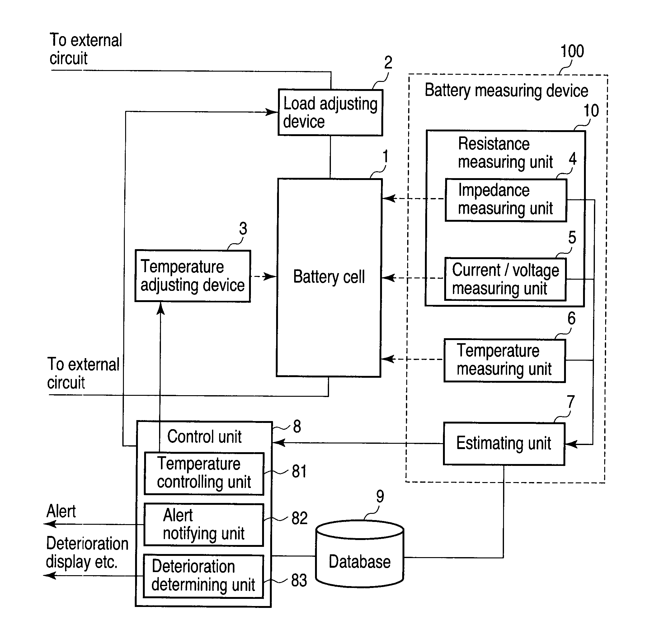
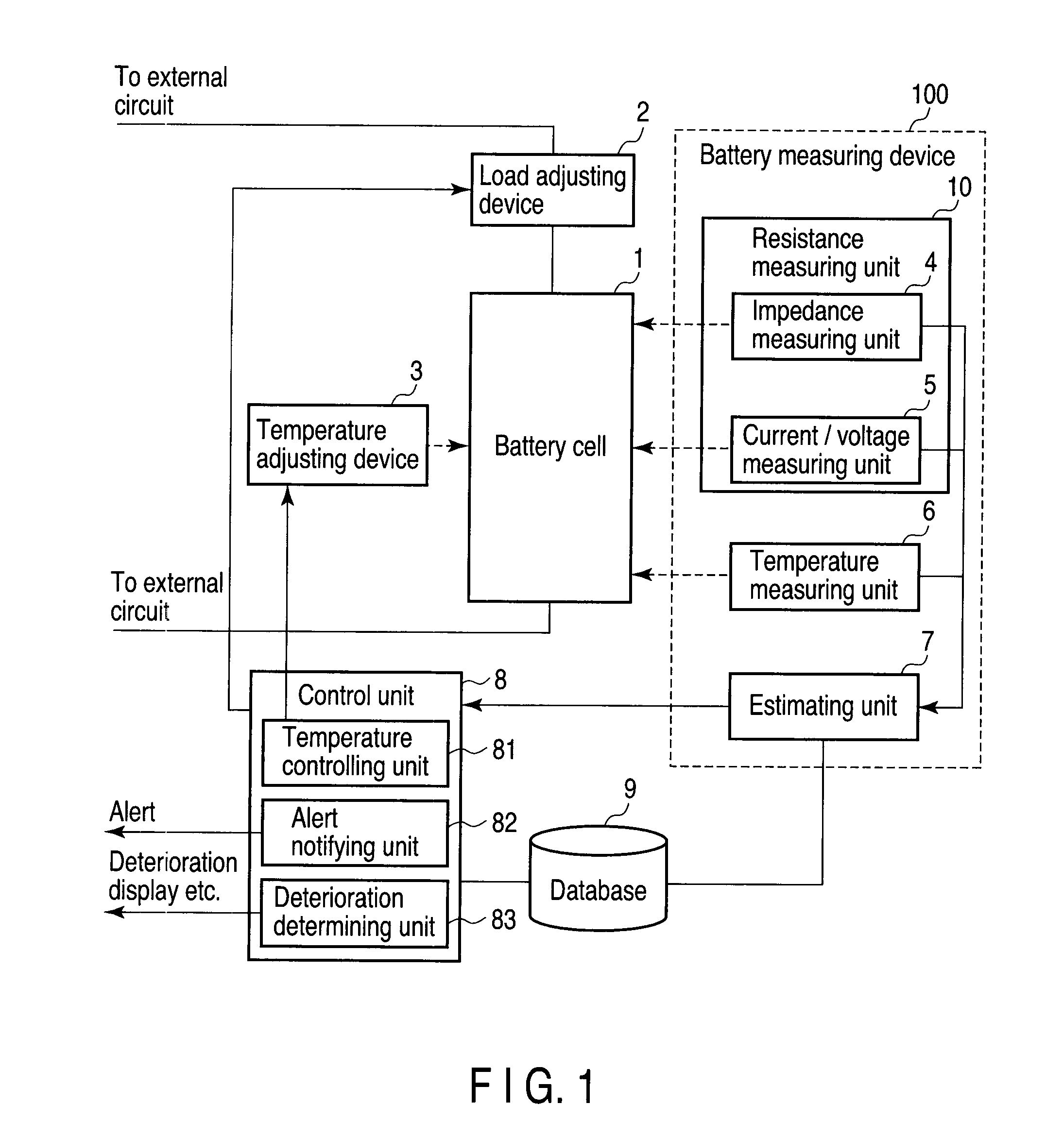
[0025]FIG. 1 shows a configuration example of a battery control system according to a first embodiment of the present invention. This battery control system includes a battery measuring device 100 which evaluates a state of a battery cell 1, and a control unit 8 which controls each device. The battery cell 1 includes a battery pack using, for example, one or a plurality of nonaqueous electrolyte secondary batteries. The system further includes a load adjusting device 2 which adjusts a load current taken out from the battery cell 1, a temperature adjusting device 3 which adjusts operating temperature of the battery cell 1, a database 9 which has control information for controlling each device and equations etc. to be explained later stored in advance, and a display unit (drawing omitted). The control unit 8 has a temperature controlling unit 81, an alert notifying unit 82,...


PUM

PropertyMeasurementUnit
temperatureaaaaaaaaaa
temperature measuringaaaaaaaaaa

Abstract

A battery measuring device includes a temperature measuring unit which measures temperature T1 of a secondary battery, a resistance measuring unit which measures an AC resistance value and a DC pulse resistance value of a first discharging period of the secondary battery at the temperature T1, and an estimating unit in which an electric resistance Re1 and a reaction resistance Rc1 of the secondary battery at the temperature T1 are considered as,
    • Re1=AC resistance value
    • Rc1=DC pulse resistance value of the first discharging period−AC resistance value, and which estimates at least an internal resistance of the secondary battery using the temperature T1, electric resistance Re1 and reaction resistance Rc1.

Description

CROSS-REFERENCE TO RELATED APPLICATIONS[0001]This application is based upon and claims the benefit of priority from prior Japanese Patent Application No. 2009-082993, filed Mar. 30, 2009, the entire contents of which are incorporated herein by reference.BACKGROUND OF THE INVENTION[0002]1. Field of the Invention[0003]The present invention is related to, for example, a device for measuring performance of a secondary battery, a battery control system and vehicle.[0004]2. Description of the Related Art[0005]A nonaqueous electrolyte secondary battery typified by a lithium ion secondary battery has high energy density and is used as a power source of various mobile electronic devices. Further, in recent years, practical use of the secondary battery is being considered for hybrid vehicles, hybrid two-wheel vehicles, electric vehicles and electric motorcycles. Secondary batteries used for vehicles such as automobiles are required a battery life of 10 to 15 years likewise the automobile itse...

Claims


Application Information

Patent Timeline
Patent Type & Authority Applications(United States)
IPC IPC(8): G06F7/00H02J7/00G01R31/36H01M10/48H01M10/60H01M10/615H01M10/625H01M10/633
CPCB60L11/1851B60L11/1861B60L2240/70G01R31/3662G01R31/3679Y02T90/16Y02T10/7005Y02T10/7011Y02T10/7044Y02T10/705Y02T10/7291H01M10/443B60L58/10B60L58/12G01R31/389G01R31/392Y02E60/10Y02T10/70Y02T10/72
Inventor MORITA, TOMOKAZUTAKAMI, NORIOINAGAKI, HIROKI
Owner KK TOSHIBA
Why Eureka
Try Eureka