
Method and system for a quick calculation of aerodynamic forces on an aircraft in transonic conditions

a technology of aerodynamic forces and transonic conditions, applied in multi-objective optimisation, instruments, cad techniques, etc., can solve the problems of poor approximation, many long and costly computations, and the need for significant computational resources for each computation

Active Publication Date: 2010-09-30
AIRBUS OPERATIONS SL +1
View PDF17 Cites 37 Cited by
  • Summary
  • Abstract
  • Description
  • Claims
  • Application Information

AI Technical Summary

Benefits of technology

[0012]It is another object of the present invention to provide methods and systems for allowing a quick calculation of the aerodynamic forces experimented by an aircraft component in transonic conditions.

Problems solved by technology

With the demand of accuracy posed in the aeronautical industry, each one of these computations requires important computational resources.
The dimensioning aerodynamic forces are not known a priori, and since the global magnitude of the forces may depend on many different flight parameters, like angle of attack, angle of sideslip, Mach number, control surface deflection angle, it has been necessary to perform many lengthy and costly computations to properly predict the maximum aerodynamic forces experimented by the different aircraft components or the complete aircraft.
However, if the snapshots used to generate the POD manifold exhibit shock waves (as must be expected in transonic conditions) that move significantly as the parameters are varied, then either (a) the resulting POD modes are stair-like shaped (instead of exhibiting the correct one-jump, shock wave shape), which yields a poor approximation, or (b) both the number of required snapshots and the dimension of the POD manifold are quite large.

Method used


Image

  • Method and system for a quick calculation of aerodynamic forces on an aircraft in transonic conditions
  • Method and system for a quick calculation of aerodynamic forces on an aircraft in transonic conditions
  • Method and system for a quick calculation of aerodynamic forces on an aircraft in transonic conditions

Examples


Embodiment Construction

[0037]An embodiment of a method and a system according to the present invention will now be described in reference to a specific example of the flow around a particular airfoil. CFD is calculated using TAU, which is a finite volume discretization of the compressible continuity, momentum, and energy equations, with viscous terms modified according to an Edwards-corrected-Spalart-Almaras turbulence model, and some stabilization terms added to avoid numerical instabilities.

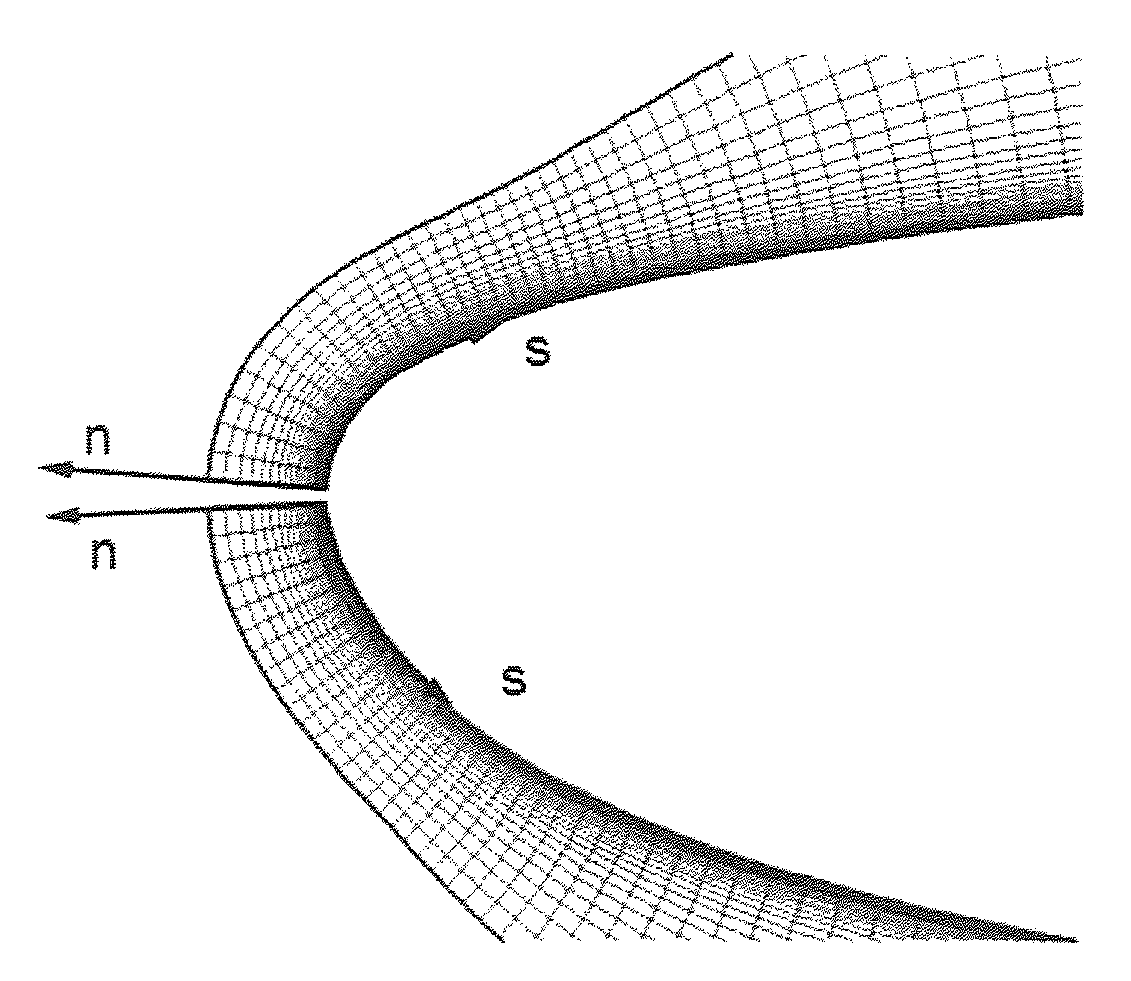
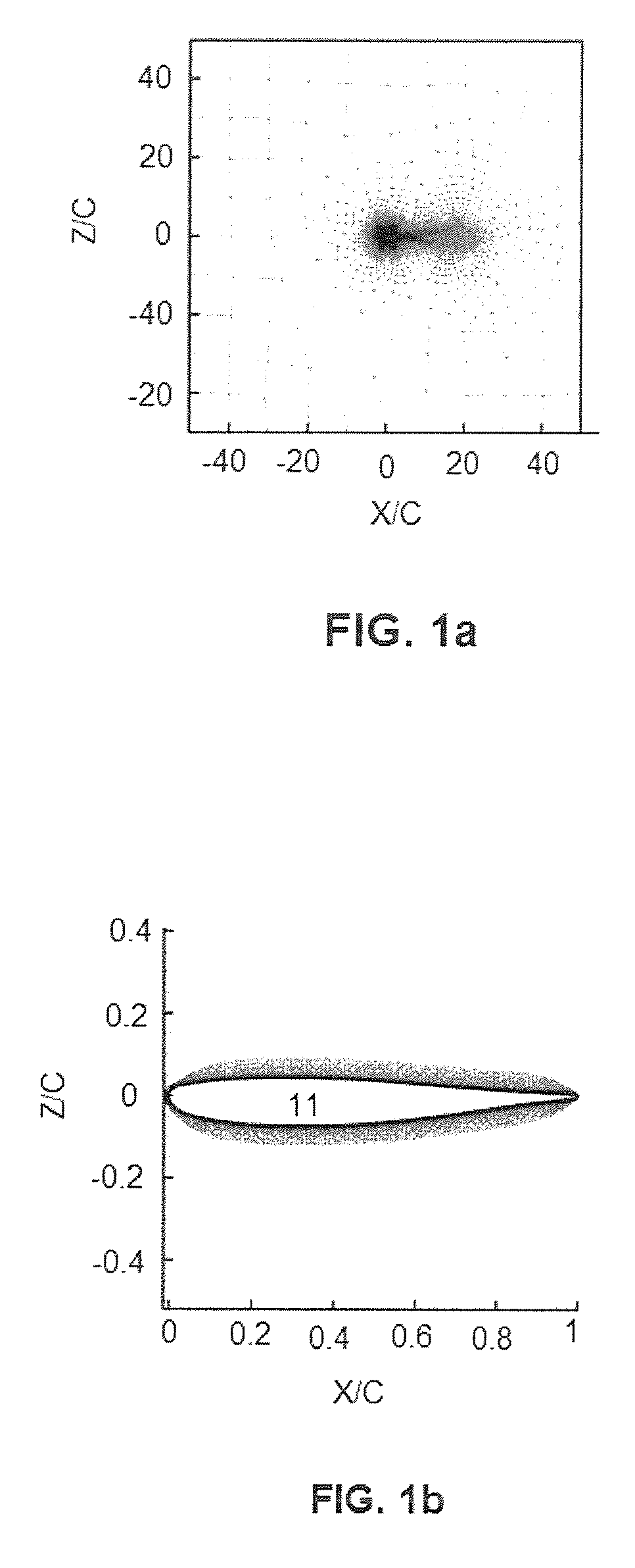
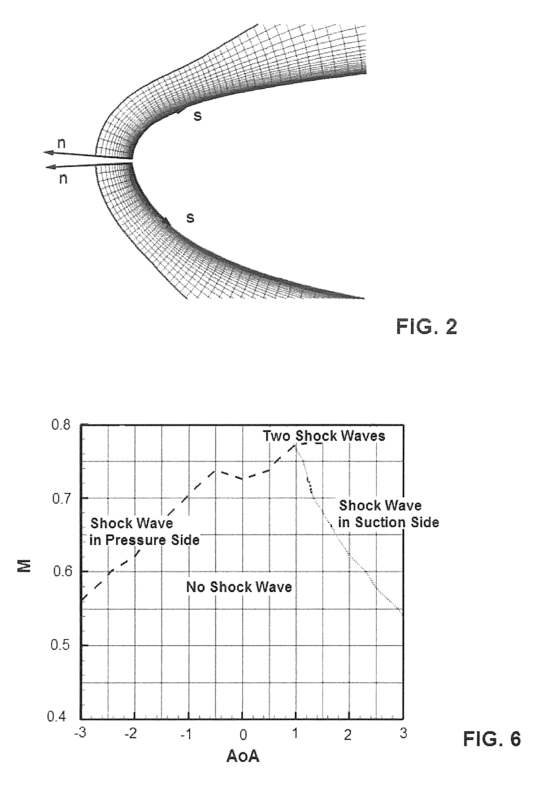
[0038]The computational domain, which contains 55,578 elements, is shown in FIG. 1a. The outer boundary domain, accounting for the freestream flow, was located 50 chords away from the airfoil. The discretization mesh consists of two parts, an O-shaped structured mesh around the airfoil (which contains 20,458 points) and an unstructured mesh outside this. Thus, some discretization errors are present near the common boundary of both meshes, which (as usually happens with industrial CFD codes) must be added to other loc...


PUM


Abstract

A computer-aided method suitable for assisting in the design of an aircraft by providing relevant dimensioning values corresponding to an aircraft component in transonic conditions inside a predefined parameter space by means of a reconstruction of the CFD computations for an initial group of points in the parameter space using a POD reduced-order model, comprising the following steps: a) Decomposing for each flow variable the complete flow field into a smooth field and a shock wave field in each of said computations; b) Obtaining the POD modes associated with the smooth field and the shock wave field considering all said computations; c) Obtaining the POD coefficients using a genetic algorithm (GA) that minimizes a fitness function; d) Calculating said dimensioning values for whatever combination of values of said parameters using the reduced-order model. The invention also refers to a system able to perform the method.

Description

FIELD OF THE INVENTION[0001]The present invention refers to methods and systems for assisting in the design of aircrafts by making calculations of the aerodynamic forces experimented by an aircraft component in transonic conditions when these forces are dependant of a significant number of parameters.BACKGROUND OF THE INVENTION[0002]A common situation in practical industrial applications related to product development is the need to perform quick surveys inside a space of state parameters. In mature and very competitive industrial sectors like aerospace, this need is motivated by the drive to generate products having good technical performance within design cycles that are as short as feasible. That is: time is a key factor in aerospace competitiveness because shortening the time market may provide a leading economic advantage during the product life cycle.[0003]In the specific case of aeronautics, the prediction of the aerodynamic forces, and more generally skin surface values dist...

Claims


Application Information

Patent Timeline
IPC IPC(8): G06F17/10G06F17/50
CPCG06F17/5018G06F17/5095G06F2217/46G06F2217/16G06F2217/08G06F2111/06G06F2113/28G06F30/15G06F2111/10G06F30/23Y02T90/00
Inventor VELAZQUEZ LOPEZ, ANGEL GERARDOFERNANDEZ, DIEGO ALONSOVEGA DE PRADA, JOSE MANUELLORENTE MANZANARES, LUIS SANTIAGODE PABLO FOUCE, VALENTIN
Owner AIRBUS OPERATIONS SL
Learn More