Method of manufacturing a heat transport device, heat transport device, electronic apparatus, and caulking pin

Inactive Publication Date: 2010-10-07
SONY CORP
View PDF17 Cites 5 Cited by
  • Summary
  • Abstract
  • Description
  • Claims
  • Application Information

AI Technical Summary

Benefits of technology

[0017]The caulking in the sealing of the injection path is crushing of an area that surrounds the injection opening of the casing. By the crushing process, an inner area in the injection path, which is communicated with the injection opening, is separated from an outer area in the injection path, which is communicated with the injection opening. Thus, at the time of welding, it is possible to suppress an influence of heat given to the outer area in the injection path, which is communicated with the injection opening.
[0018]The caulking in the sealing of the injection path may be performed on an area on the injection path outside an area that surrounds the injection opening. That is, because the caulked area is distanced from the injection opening from the injection opening, it is possible to suppress an influence of heat given to the caulked area of the casing at the time of welding.
[0019]The contacting may be performed under an atmospheric pressure after the sealing of the injection path. Because the contacting process can be performed under the atmospheric pressure, it becomes easy

Problems solved by technology

In the heat pipe disclosed in Patent Document 1, the thermoplastic metal is used as a sealing member for the hole, which has a problem of low reliability of airtightness in the heat pipe.
In this case, the the

Method used


Image

  • Method of manufacturing a heat transport device, heat transport device, electronic apparatus, and caulking pin
  • Method of manufacturing a heat transport device, heat transport device, electronic apparatus, and caulking pin
  • Method of manufacturing a heat transport device, heat transport device, electronic apparatus, and caulking pin

Examples


Example

First Embodiment

Structure of Heat Transport Device

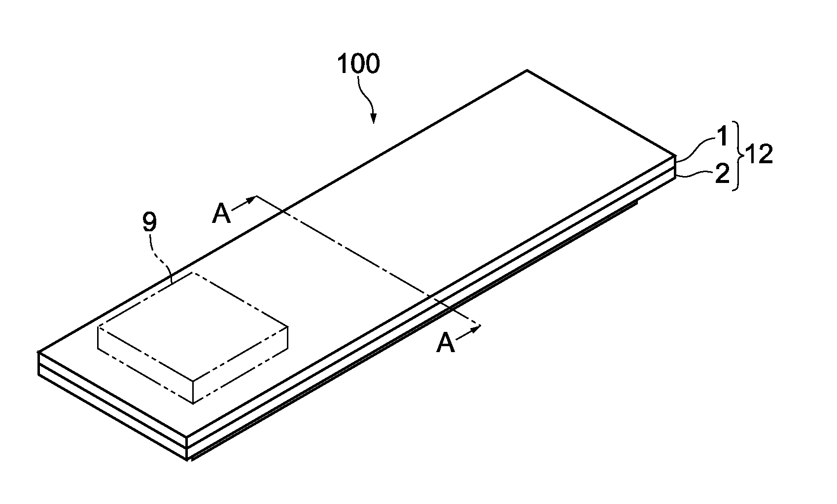
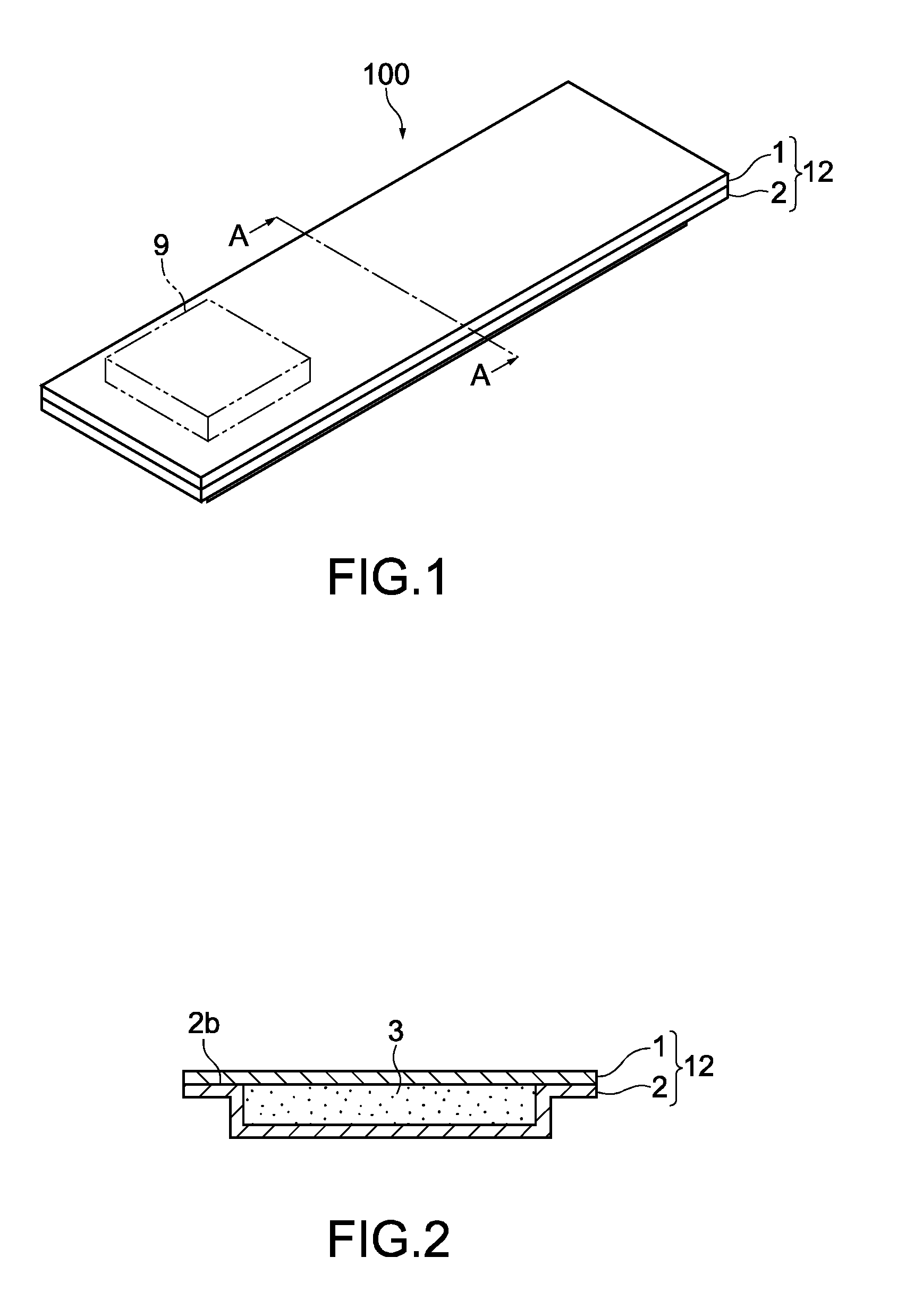
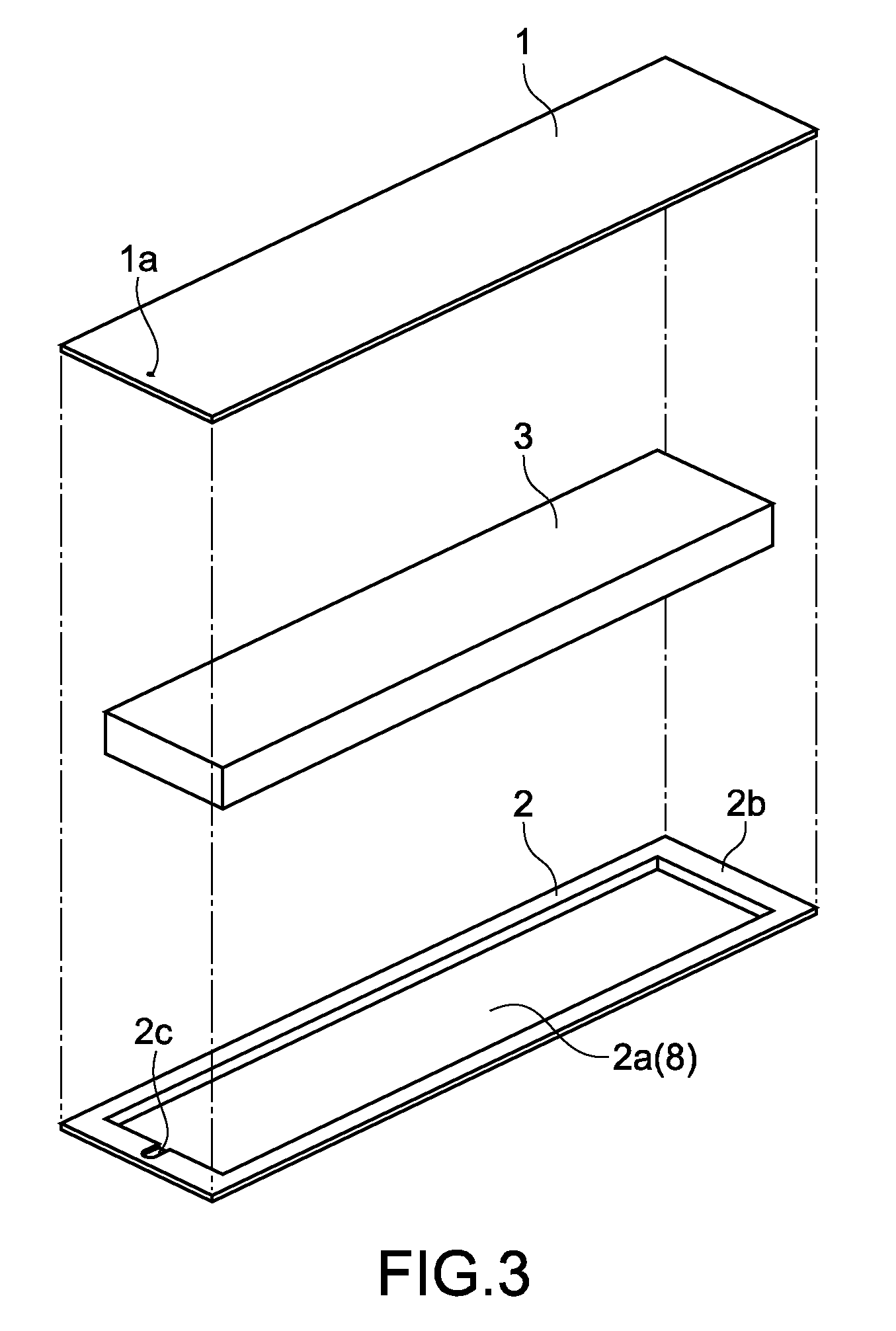
[0071]FIG. 1 is a perspective view showing a heat transport device 100 according to a first embodiment of the present invention. FIG. 2 is a cross-sectional view showing the heat transport device 100 taken along a line perpendicular to a longitudinal direction of the heat transport device 100 shown in FIG. 1 (taken along the line A-A of FIG. 1). FIG. 3 is a perspective view of the heat transport device 100 in a manufacturing process.

[0072]The heat transport device 100 includes a flat plate 1, a capillary member 3, a vapor flow path (not shown), and a dish-like container plate 2 having a concave portion 2a in which the capillary member 3 and the vapor flow path are contained. The flat plate 1, the capillary member 3, and the container plate 2 are formed into a rectangular shape, for example. The flat plate 1 and the container plate 2 constitute a casing 12 of the heat transport device 100.

[0073]In the casing 12, a working fluid (not s...

Example

Second Embodiment

[0105]FIG. 10 is an enlarged plan view showing an area in the vicinity of an injection opening 31a of a heat transport device 200 according to a second embodiment. In the following, descriptions on the same portions and functions as those of the heat transport device 100 according to the first embodiment shown in FIG. 1 and the like will be simplified or omitted, and descriptions on different points will be mainly given.

[0106]An injection path 33 of a casing 32 of the heat transport device 200 has an L-letter shape and is connected to an edge portion 8a of the action area 8, thereby allowing the injection path 33 and the action area 8 to communicate with each other. Like the heat transport device 100 according to the first embodiment, the heat transport device 200 includes a flat plate 31 having the injection opening 31a, a container plate having the L-letter shaped injection path 33, and the capillary member 3 (see, FIG. 3).

[0107]FIG. 11 is a flowchart showing a ma...

Example

Third Embodiment

[0113]FIG. 12 is an enlarged plan view showing an area in the vicinity of an injection opening of a heat transport device according to a third embodiment of the present invention. In a case where a linear, elongated injection path 19 shown in the figure is provided to a casing 17, the casing is circularly crushed by the manufacturing method described in the second embodiment, a temporary sealing groove 18b is formed on a flat plate 18. As a result, the same effect as in the second embodiment can be obtained.


PUM

PropertyMeasurementUnit
Pressureaaaaaaaaaa
Areaaaaaaaaaaa
Distanceaaaaaaaaaa

Abstract

A method of manufacturing a heat transport device includes injecting a working fluid that transports heat by a phase change into a casing through an injection opening of the casing under reduced pressure, sealing an injection path by caulking under the reduced pressure, the injection path being provided in the casing into which the working fluid is injected and causing the injection opening and an action area in which the phase change of the working fluid occurs to communicate with each other, contacting a peripheral area of the injection opening of the casing with an inner surface of the injection path by caulking the peripheral area, the peripheral area including the injection opening, and sealing the injection opening by welding a part of the casing contacted.

Description

BACKGROUND OF THE INVENTION[0001]1. Field of the Invention[0002]The present invention relates to a heat transport device that transports heat by a phase change of a working fluid, and to a manufacturing method of the same, an electronic apparatus equipped with a heat transport device, and a caulking pin.[0003]2. Description of the Related Art[0004]In the past, a flat-plate heat pipe has been widely used as a device that cools a heat source such as a CPU (central processing unit). A flat-plate heat pipe cools a CPU and the like by using a phase change of a working fluid, and therefore contains a working fluid therein.[0005]For example, Japanese Patent Application Laid-open No. 2007-315745 (hereinafter, referred to as Patent Document 1) discloses a flat-plate heat pipe, on an outer surface of which a refrigerant injection hole and an air outlet hole are formed. In the flat-plate heat pipe, a refrigerant such as water is injected through the refrigerant injection hole, and then a therm...

Claims


Application Information

Patent Timeline
IPC IPC(8): B21D53/02
CPCF28D15/0233F28D15/0283H01L23/427Y10T29/4935H01L2924/0002H01L2924/00
Inventor YAJIMA, TAKASHIGOTO, KAZUOYAMASHITA, KEITAROSAKAMOTO, KAZUYA
Owner SONY CORP
Why Eureka
Try Eureka