Centerbody for mixer assembly of a gas turbine engine combustor

a gas turbine engine and mixer technology, applied in the direction of machines/engines, mechanical equipment, lighting and heating apparatus, etc., can solve the problems of reducing the production of undesirable combustion products, reducing the power output, and reducing the production of hc and co

Inactive Publication Date: 2010-10-07
GENERAL ELECTRIC CO
View PDF5 Cites 40 Cited by
  • Summary
  • Abstract
  • Description
  • Claims
  • Application Information

AI Technical Summary

Problems solved by technology

Balancing the operation of a combustor to allow efficient thermal operation of the engine, while simultaneously minimizing the production of undesirable combustion products, is difficult to achieve.
In that regard, operating at low combustion temperatures to lower the emissions of NOx can also result in incomplete or partially incomplete combustion, which can lead to the production of excessive amounts of HC and CO, as well as lower power output and lower thermal efficiency.
It has been found that the separate air circuits for the pilot mixer and the main mixer unnecessarily occupy precious space in the mixer assembly.
Further, the aft end of the centerbody adjacent the main mixer is subject to overheating and possible damage.

Method used


Image

  • Centerbody for mixer assembly of a gas turbine engine combustor
  • Centerbody for mixer assembly of a gas turbine engine combustor
  • Centerbody for mixer assembly of a gas turbine engine combustor

Examples


Embodiment Construction

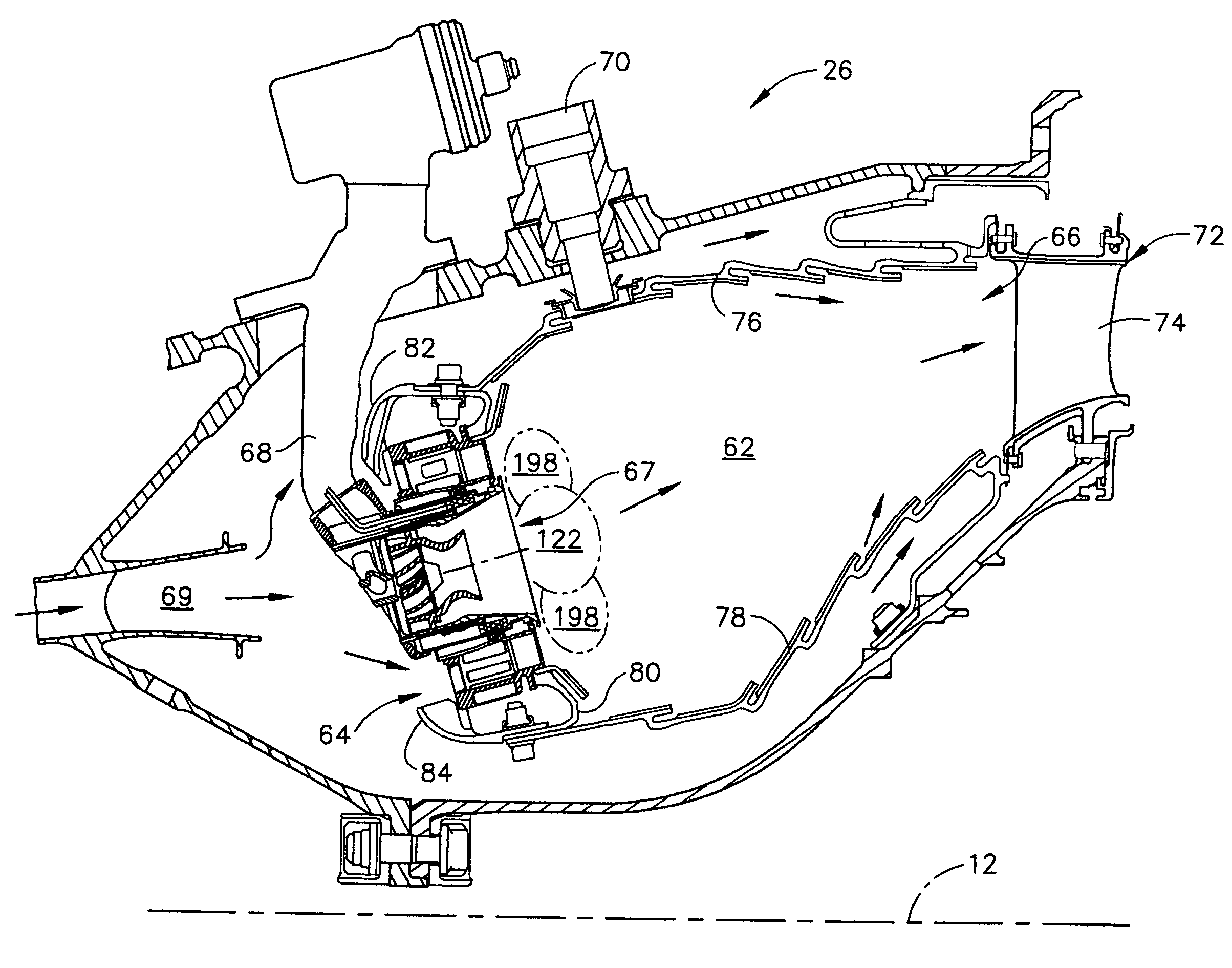
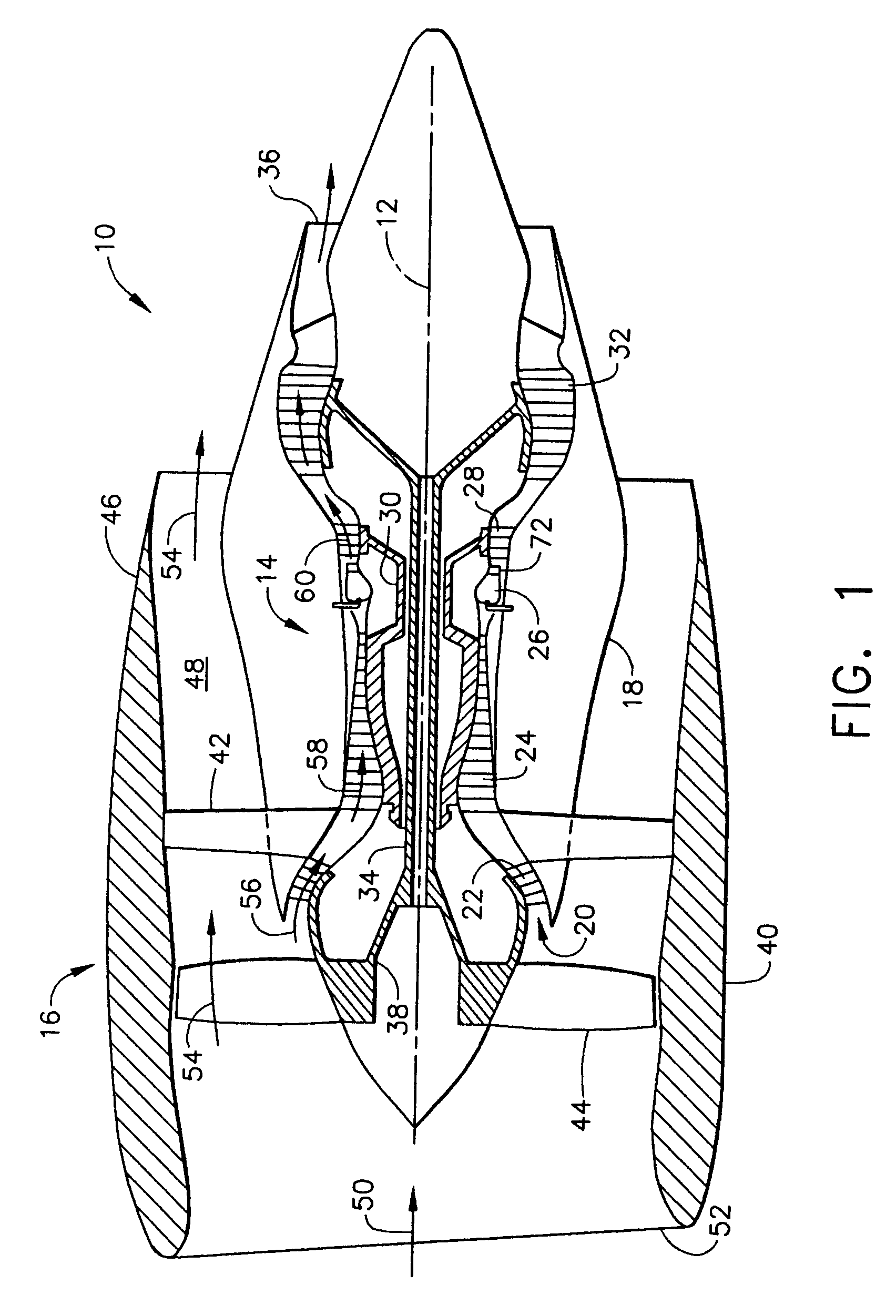
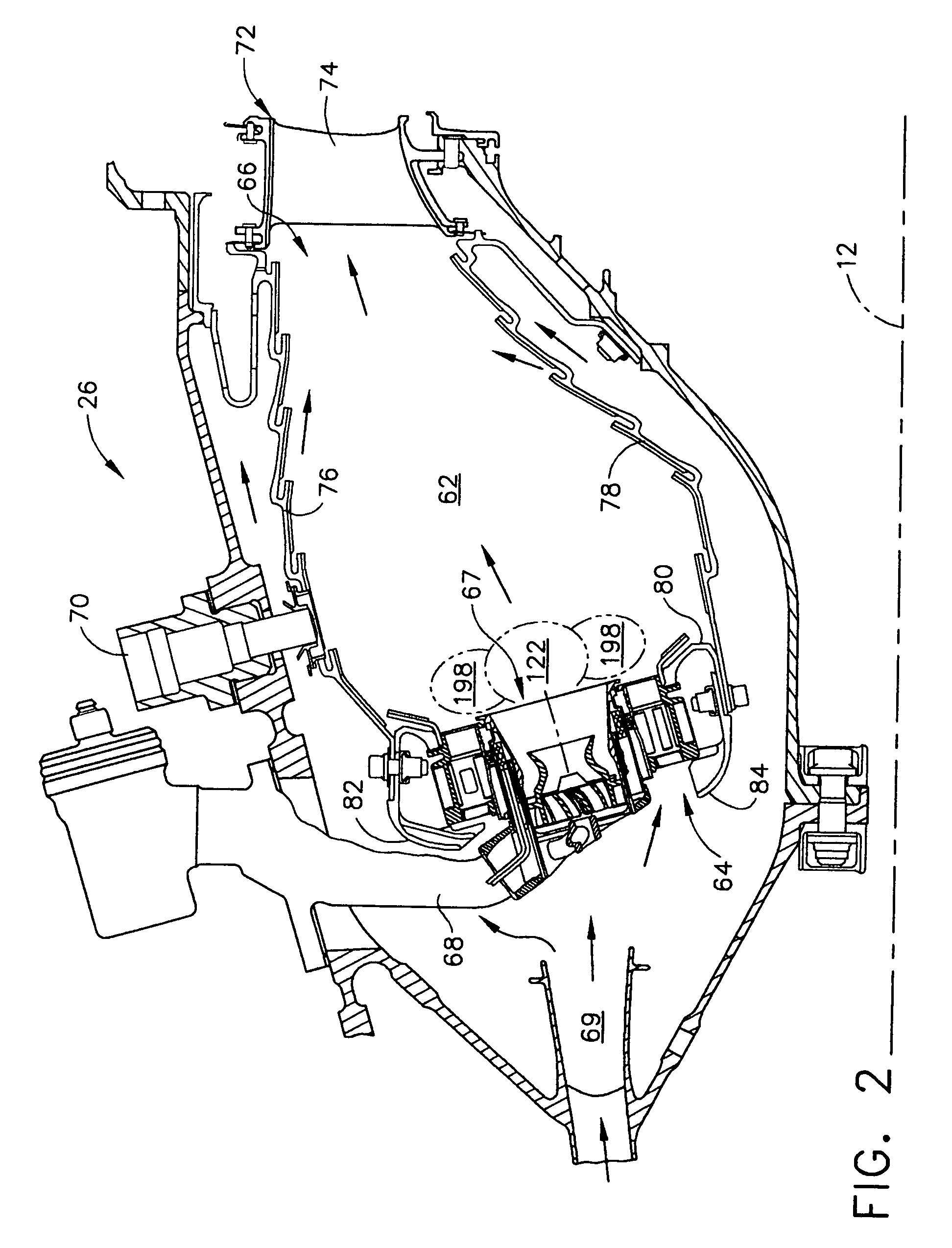
[0015]Referring now to the drawings in detail, wherein identical numerals indicate the same elements throughout the figures, FIG. 1 depicts in diagrammatic form an exemplary gas turbine engine 10 (high bypass type) utilized with aircraft having a longitudinal or axial centerline axis 12 therethrough for reference purposes. Engine 10 preferably includes a core gas turbine engine generally identified by numeral 14 and a fan section 16 positioned upstream thereof. Core engine 14 typically includes a generally tubular outer casing 18 that defines an annular inlet 20. Outer casing 18 further encloses and supports a booster compressor 22 for raising the pressure of the air that enters core engine 14 to a first pressure level. A high pressure, multi-stage, axial-flow compressor 24 receives pressurized air from booster 22 and further increases the pressure of the air. The pressurized air flows to a combustor 26, where fuel is injected into the pressurized air stream to raise the temperature...


PUM


Abstract

A mixer assembly for use in a combustion chamber of a gas turbine engine includes a pilot mixer, a main mixer and a centerbody positioned between the pilot mixer and the main mixer. The pilot mixer includes an annular pilot housing having a hollow interior and a pilot fuel nozzle mounted in the housing and adapted for dispensing droplets of fuel to the hollow interior of the pilot housing. The main mixer includes: a main housing surrounding the pilot housing and defining an annular cavity; a plurality of fuel injection ports for introducing fuel into the annular cavity; and, a swirler arrangement including at least one swirler positioned upstream from the fuel injection ports, wherein each swirler of the arrangement has a plurality of vanes for swirling air traveling through such swirler to mix air and the droplets of fuel dispensed by the fuel injection ports. The centerbody includes a fuel manifold therein for providing fuel to the fuel injection ports and an air manifold therein for providing air to an aft portion of the pilot mixer and/or the aft portion of the annular cavity in the main mixer.

Description

BACKGROUND OF THE INVENTION[0001]The present invention relates to a staged combustion system in which the production of undesirable combustion product components is minimized over the engine operating regime and, more particularly, to a centerbody between the main mixer and the pilot mixer which includes an air manifold for supplying air to the main mixer and the pilot mixer.[0002]Air pollution concerns worldwide have led to stricter emissions standards both domestically and internationally. Aircraft are governed by both Environmental Protection Agency (EPA) and International Civil Aviation Organization (ICAO) standards. These standards regulate the emission of oxides of nitrogen (NOx), unburned hydrocarbons (HC), and carbon monoxide (CO) from aircraft in the vicinity of airports, where they contribute to urban photochemical smog problems. Such standards are driving the design of gas turbine engine combustors, which also must be able to accommodate the desire for efficient, low cost...

Claims


Application Information

Patent Timeline
Patent Type & Authority Applications(United States)
IPC IPC(8): F02C7/22F02C7/12
CPCF23R3/14Y02T50/675F23R3/343F23R3/286Y02T50/60F23D11/383F23D11/40
Inventor MANCINI, ALFRED ALBERTMONGIA, HUKAM CHAND
Owner GENERAL ELECTRIC CO
Why Eureka
Try Eureka