Engine bench system control system

a control system and engine technology, applied in the direction of engine testing, structural/machine measurement, instruments, etc., can solve the problems of difficult to achieve a stable torque control based on the p design method, and the determination of a weight function requires trial and error

Active Publication Date: 2010-10-07
MEIDENSHA ELECTRIC MFG CO LTD
View PDF7 Cites 18 Cited by
  • Summary
  • Abstract
  • Description
  • Claims
  • Application Information

AI Technical Summary

Benefits of technology

[0016]In this way, the present invention is implemented by: expressing an engine bench system as a two-inertia mechanical system model; obtaining a fourth-order polynomial as a closed-loop characteristic polynomial of the motion equations of this mechanical system model and the transfer function of

Problems solved by technology

The determination of a weight function requires trial and error.
However, in a case where the spring rigidity significantly varies, for

Method used


Image

  • Engine bench system control system
  • Engine bench system control system
  • Engine bench system control system

Examples


embodiment 1

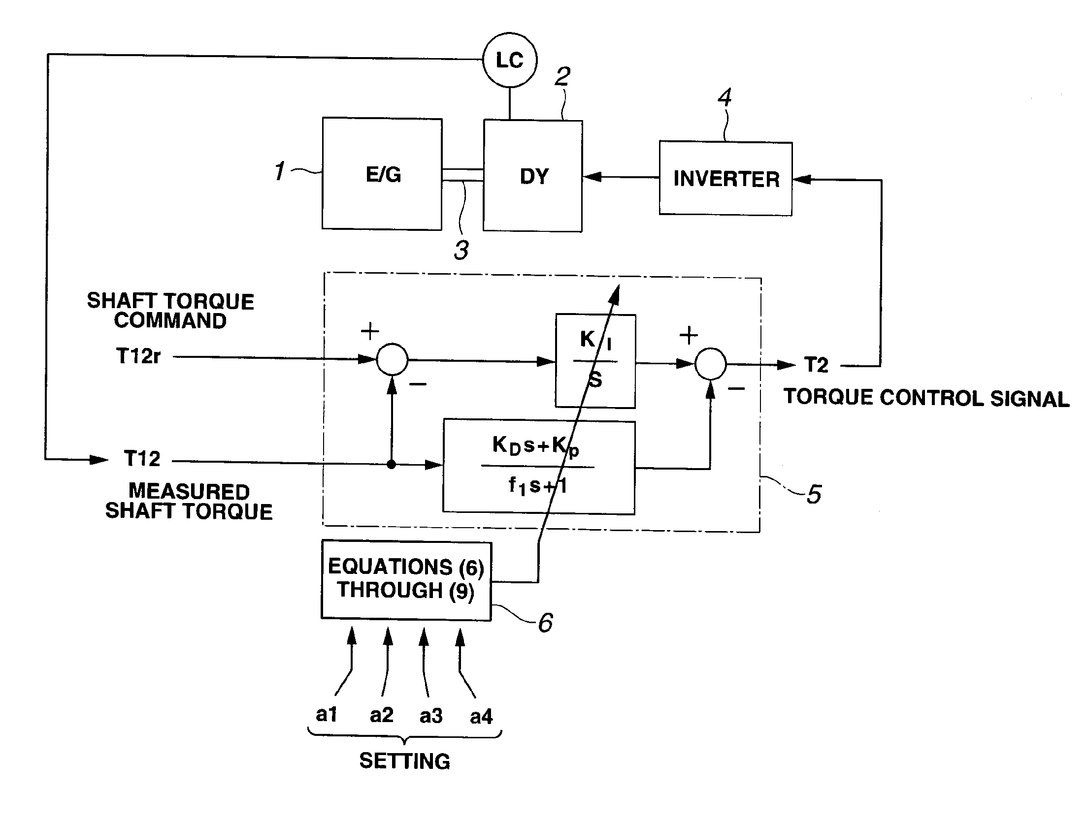
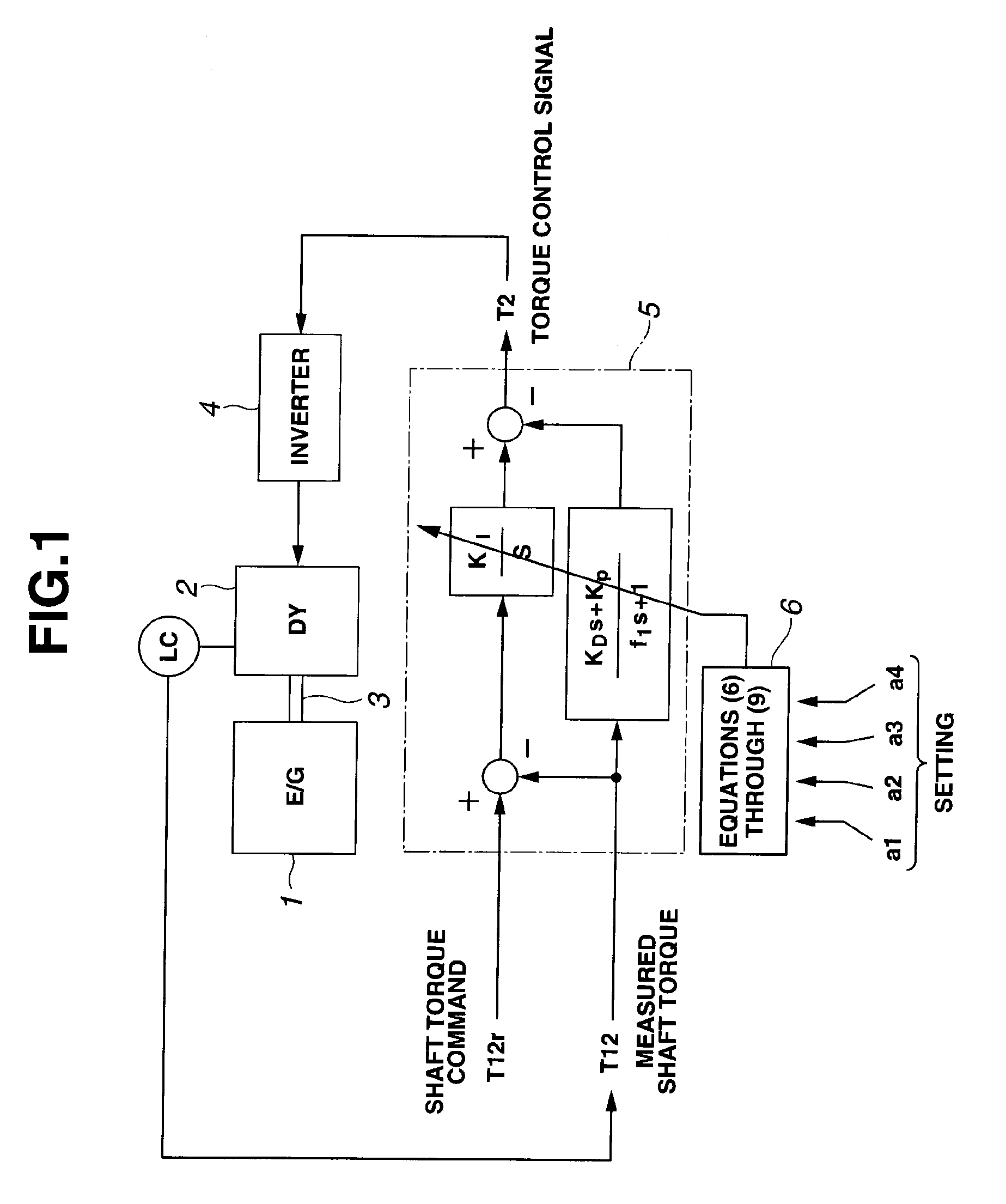
[0044]FIG. 1 shows a control circuit of a major part of a dynamometer in an engine bench system according to the present embodiment. In a system configuration where an engine 1 is coupled to a dynamometer 2 via a shaft 3, and an inverter 4 controls an output of engine 1 and a torque of dynamometer 2, a controller 5 generates a torque control signal T2 for dynamometer 2 by calculation based on a shaft torque command T12r and a measured shaft torque T12 with a transfer function of the above equation (4).

[0045]Control parameters (KI, KP, KD, f1) in controller 5 are determined by calculation according to the above equations (6) through (9) on a basis of control characteristic parameters (a4, a3, a2, a1) set in a function calculation section 6 and estimated controlled object parameters (J1, K12, J2).

[0046]In this embodiment, the coefficients (KI, KP, KD, f1) of equation (4) are determined as follows.

[0047]Control characteristic parameters (a4, a3, a2, a1) are prepared by a parameter sett...

embodiment 2

[0054]FIG. 5 shows a control circuit of a major part of a dynamometer according to the present embodiment, in which the mechanical system is omitted. In this embodiment, a parameter calculation section 7 is provided which determines parameters of (KI, KP, KD, f1) in equation (4) as described below.

[0055]Parameter calculation section 7 sets control characteristic parameters (a4, a3, a2, a1) to coefficients of a product of a characteristic polynomial of a two-inertia mechanical system having a resonance characteristic and a characteristic polynomial of a second-order low-pass filter. Specifically, the control characteristic parameters are set as follows.

[0056]When a resonance frequency and a damping coefficient of a two-inertia mechanical system having a desired resonance characteristic are represented by ωn, and z, respectively, its characteristic polynomial is (s / ωn)2+2×z×(s / ωn)+1. In addition, the characteristic polynomial of the second-order low pass filter is assumed as c2×s2+c1×...

embodiment 3

[0060]FIG. 7 shows a control circuit block diagram of a major part of a dynamometer according to the present embodiment, in which the mechanical system is omitted. In this embodiment, a parameter calculation section 8 is provided to determine control parameters of (KI, KP, KD, f1) in equation (4) as follows.

[0061]Parameter calculation section 8 sets control characteristic parameters (a4, a3, a2, a1) to coefficients of a product of the characteristic polynomial of a two-inertia system having a resonance characteristic A and the characteristic polynomial of a two-inertia system having a resonance characteristic B.

[0062]Specifically, control characteristics are set as follows. When the resonance characteristic A is represented by a resonance frequency ωn1 [rad / a], and a damping coefficient z1, and the resonance characteristic B is represented by a resonance frequency of ωn2 [rad / a], and a damping coefficient z2, the product of these characteristic polynomials is ((s / ωn1)2+2×z1×(s / ωn1)+...


PUM


Abstract

It is a challenge to make it possible to produce a resonance suppression effect, and perform a stable control even in a case where a spring rigidity of a shaft significantly varies. The challenge is achieved as follows. In an engine bench system in which an engine 1 to be tested and a dynamometer 2 are coupled together by a coupling shaft 3, and a shaft torque control of the dynamometer is performed, a controller 5 includes: an integral element having an integral coefficient KI for a deviation (T12r−T12) between a shaft torque command T12r and a measured shaft torque T12; a differential element having a differential coefficient KD for the measured shaft torque T12; and a proportional element KP for the measured shaft torque T12. The controller 5 obtains a torque control signal T2 by subtracting the differential element and the proportional element from the integral element. Control parameters (KI, KP, KD, f1) are determined according to control characteristic parameters (a4, a3, a2, a1) set in a function calculation section 6, inertia moments J1, J2 of the engine and the dynamometer, and spring rigidity K12 of the coupling shaft.

Description

TECHNICAL FIELD[0001]The present invention relates to an engine bench system control system in which an engine to be tested is directly coupled to a dynamometer as a power absorber, and various kinds of characteristics of the engine are measured, and particularly relates to a torque control for the dynamometer.BACKGROUND ART[0002]FIG. 13 shows an engine bench system. In FIG. 13, an engine E / G is combined with a transmission T / M (AT or MT with a clutch) which is connected with dynamometer DY via a coupling shaft. Engine E / G is provided with a throttle actuator ACT for controlling throttle opening.[0003]On the other hand, dynamometer DY is provided with a revolution detector PP and a torque detector (a load cell) LC. The speed or torque of dynamometer DY are controlled on a basis of detection signals of the detectors. This control is implemented by a PID control with a controller (a dynamometer controller) C(s). FIG. 13 shows a case of torque control, where controller C(s) performs a ...

Claims


Application Information

Patent Timeline
IPC IPC(8): G01M15/00
CPCG01M15/02
Inventor AKIYAMA, TAKAOSAWADA, YOSHIMASAKANKE, MASAYASU
Owner MEIDENSHA ELECTRIC MFG CO LTD
Why Eureka
Try Eureka