
Apparatus for Recycling Noble Metals

a noble metal and recycling technology, applied in the field of recycling apparatuses, can solve the problems of no apparatus that can recycle noble metals systematically, pollute the environment, etc., and achieve the effect of increasing the amount of noble metals recycled and speeding up recycling

Inactive Publication Date: 2010-10-07
SINGWEI TECH CO LTD
View PDF5 Cites 1 Cited by
  • Summary
  • Abstract
  • Description
  • Claims
  • Application Information

AI Technical Summary

Benefits of technology

[0006]An objective of the present invention is to provide an apparatus for recycling noble metals, which can recycle noble metals continuously. Thereby, the speed of recycling is enhanced, and the amount of recycled noble metals is increased as well.
[0007]Another objective of the present invention is to provide an apparatus for recycling noble metals, which can recycle noble metals automatically.
[0008]Still another objective of the present invention is to provide an apparatus for recycling noble metals. The devices in the apparatus for recycling noble metals are arranged in U-shape. Thereby, adding an object containing noble metals or pouring the object containing noble metals can be performed on the same side of the apparatus for recycling noble metals. Hence, a user needs not to operate on both sides of the apparatus for recycling noble metals, enhancing ease of operation.

Problems solved by technology

If the waste is not recycled and processed appropriately, the environment will be polluted and, from the perspective of fully utilizing the noble metals, it is invisible squander.
However, because palladium is costly, it is important to recycle and reuse palladium effectively during the development of multilayer materials using palladium alloys.
Currently, there is no apparatus that can recycle noble metals systematically.

Method used


Image

  • Apparatus for Recycling Noble Metals
  • Apparatus for Recycling Noble Metals
  • Apparatus for Recycling Noble Metals

Examples


Embodiment Construction

[0017]In order to make the structure and characteristics as well as the effectiveness of the present invention to be further understood and recognized, the detailed description of the present invention is provided as follows along with preferred embodiments and accompanying figures.

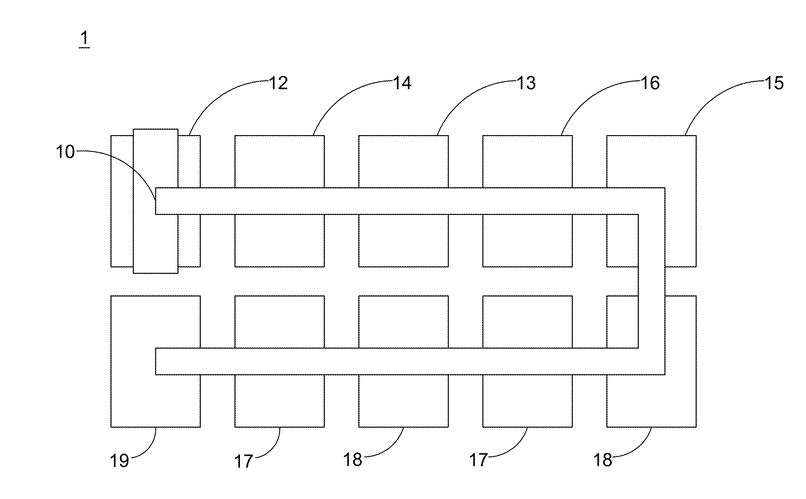
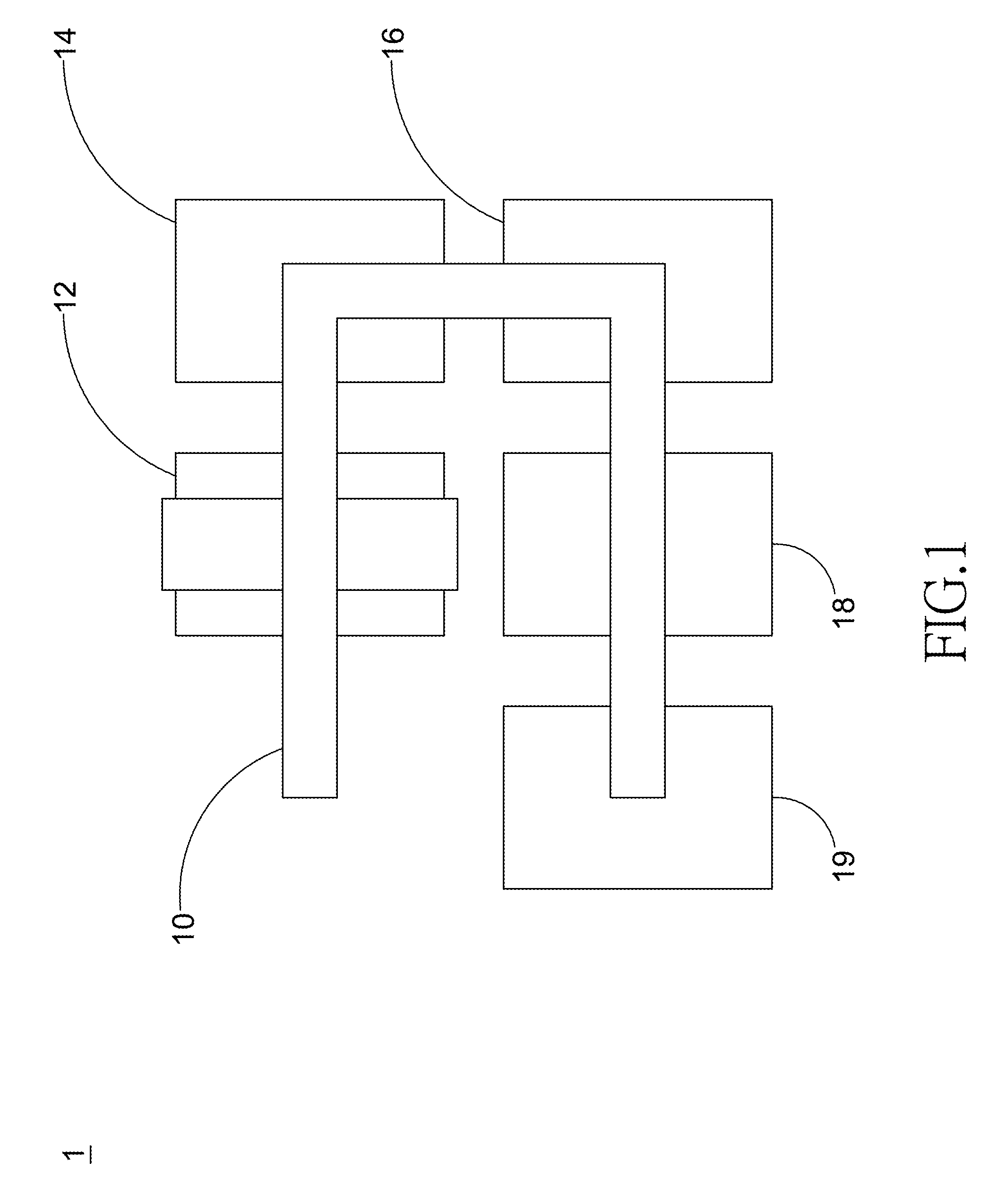
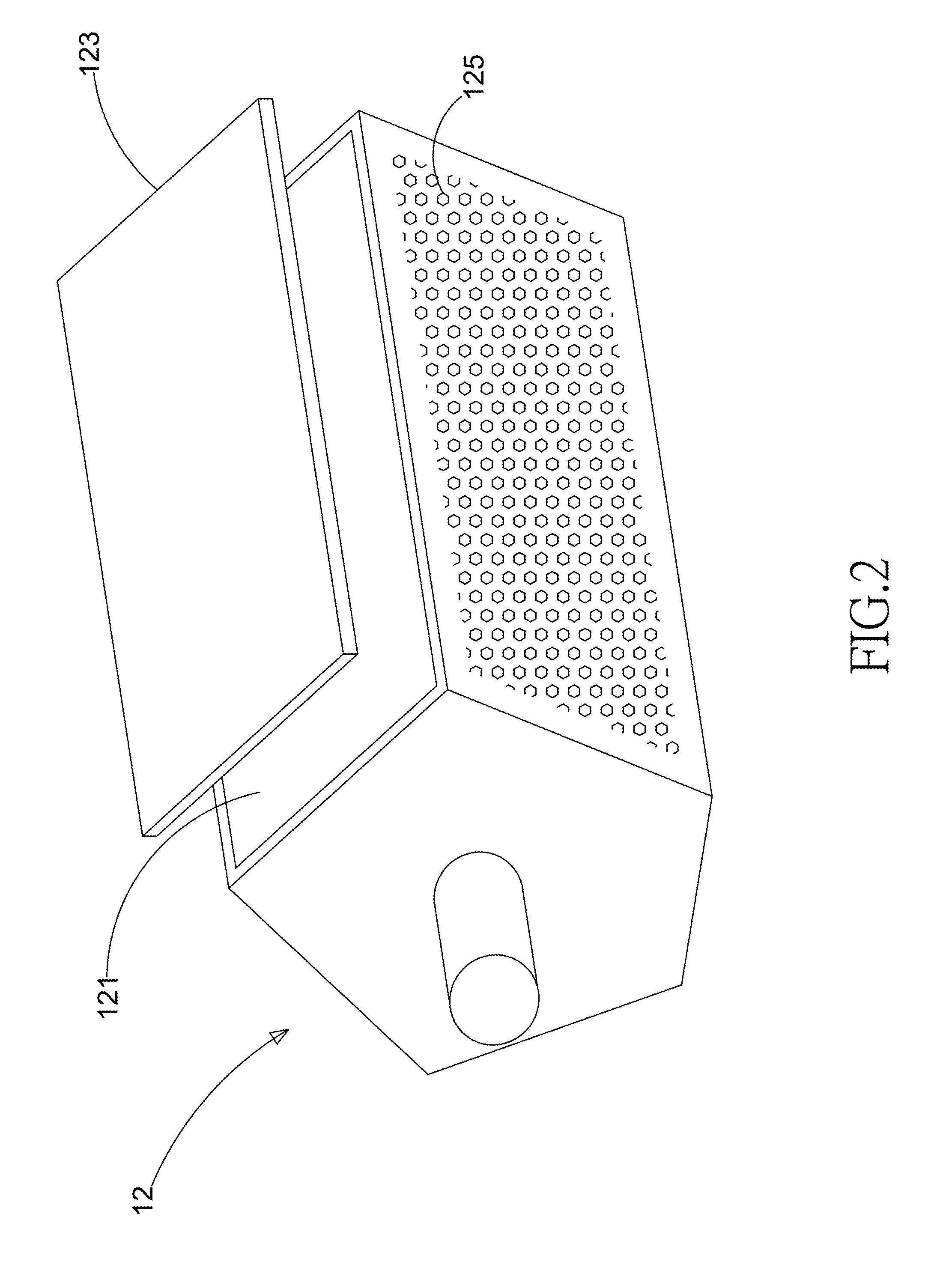
[0018]FIG. 1 shows a schematic diagram of an apparatus according to a preferred embodiment of the present invention. As shown in the figure, the present invention provides an apparatus for recycling noble metals 1, which comprises one or more conveyers 10, one or more carriers 12, an immersion device 14, one or more dissolution devices 16, and one or more rinse devices 18. The conveyer 10 is a hoist, used for conveying the carrier 12 to the immersion device 14, the dissolution devices 16, or the rinse devices 18. The carriers 12, the immersion device 14, the dissolution devices 16, and the rinse devices 18 are arranged in U-shape. The conveyer 10 is a hoist, used for conveying the carrier 12 to the immers...


PUM

PropertyMeasurementUnit
conductivityaaaaaaaaaa
reactivityaaaaaaaaaa
temperaturesaaaaaaaaaa

Abstract

The present invention provides an apparatus for recycling noble metals, which comprises one or more conveyers, one or more carriers, an immersion device, one or more dissolution devices, and one or more rinse devices. The carriers, the immersion device, the dissolution devices, and the rinse devices are arranged in U-shape. Thereby, adding an object containing noble metals or pouring the object containing noble metals can be performed on the same side of the apparatus for recycling noble metals. Hence, a user needs not to operate on both sides of the apparatus for recycling noble metals, enhancing ease of operation. The carriers carry objects containing noble metals. The conveyer is used for conveying the carriers to the immersion device, the dissolution devices, and the rinse devices sequentially for recycling noble metals from the objects containing noble metals. The apparatus according to the present invention can recycle noble metals continuously. Thereby, the speed of recycling is enhanced, and the amount of recycled noble metals is increased as well.

Description

FIELD OF THE INVENTION[0001]The present invention relates to a recycling apparatus, and particularly to an apparatus for recycling noble metals.BACKGROUND OF THE INVENTION[0002]With advancement of technologies, the electronics industry develops prosperously. Waste derived from electronic components increases daily. The waste includes integrated circuits, printed circuit board, resistors, or capacitors, and comprising elements of copper, lead, aluminum, iron, and noble metals. If the waste is not recycled and processed appropriately, the environment will be polluted and, from the perspective of fully utilizing the noble metals, it is invisible squander.[0003]The recycling process of waste containing metals is mainly focused on recycling and reusing valuable metals including high-priced noble metals such as gold and palladium. For example, the waste containing gold comes from the integrated circuit industry and the printed circuit board industry. In the processes of thin-film depositi...

Claims


Application Information

Patent Timeline
Patent Type & Authority Applications(United States)
IPC IPC(8): B01J19/00B01D11/02
CPCC22B3/02C22B11/046C22B11/042C22B7/006Y02P10/20
Inventor YANG, CHIN-HSIUNGTSAI, HSIN-YI
Owner SINGWEI TECH CO LTD
Learn More