

Anti-reflective and light-trapping solar module package structure
a solar module and package technology, applied in the field of package structure, can solve the problems of low solar power output, complex fabrication process, low efficiency of most approaches, etc., and achieve the effects of high transmittance, high light-trapping effect, and enhanced solar power output or photovoltaic efficiency of the solar module package structur
- Summary
- Abstract
- Description
- Claims
- Application Information
AI Technical Summary
Benefits of technology
Problems solved by technology
Method used
Image

Examples
example 1
General, Surface-Mounted Type Package Structure
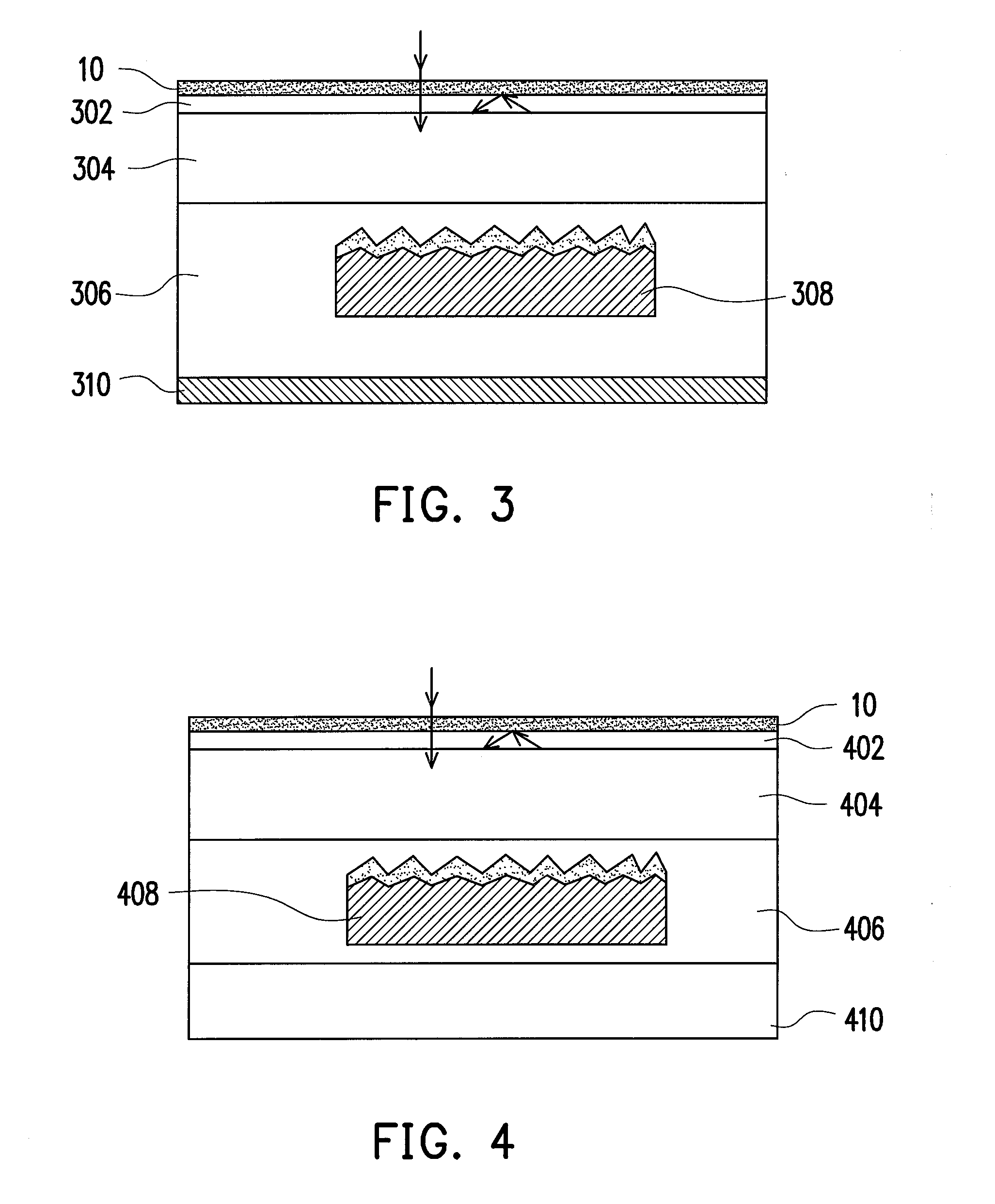
[0038]One optical sheet is mounted on the front surface of the general type package structure, as shown in FIG. 3. The new laminate structure is designed as: (optical sheet 10 / encapsulant 302 / glass plate 304 / encapsulant 306 / solar cell 308 / encapsulant 306 / highly reflective back-sheet 310) (from the front to the back). According to the present pressing processes, the above laminate structure is placed into the laminator at 165.0° C. and a vacuum in 10−2 ton is drawn from the upper and lower chambers for 8 minutes in total. Next, the vacuum of the upper chamber is broken for 8 minutes and the solar module package structure is pressed and sealed. The above laminate structure can be fabricated by employing the pressing processes compatible with the currently used laminator machinery.
[0039]For example, the material(s) of the encapsulant 302 / 306 can be selected from ethylene vinyl acetate (EVA) or polyvinyl butyral (PVB), while the glass plate...
example 2
Transparent, Surface-Mounted Type Package Structure
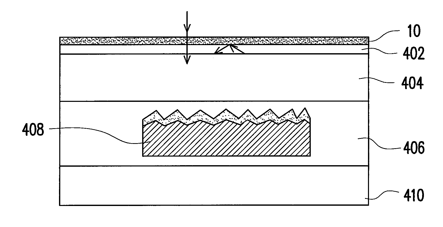
[0041]One optical sheet is mounted on the front surface of the transparent type package structure, as shown in FIG. 4. The new laminate structure is designed as: (optical sheet 10 / encapsulant 402 / glass plate 404 / encapsulant 406 / solar cell 408 / encapsulant 406 / glass back plate 410) (from the front to the back). According to the present pressing processes, the above laminate structure is placed into the laminator at 165.0° C. and a vacuum in 10−2 torr is drawn from the upper and lower chambers for 8 minutes in total. Next, the vacuum of the upper chamber is broken for 8 minutes and the solar module package structure is pressed and sealed. The above laminate structure can be fabricated by employing the pressing processes compatible with the currently used laminator machinery.
[0042]For example, the material(s) of the encapsulant 402 / 406 can be selected from ethylene vinyl acetate (EVA) or polyvinyl butyral (PVB), while the glass plate 40...
example 3
General, Inter-Layered Type Package Structure
[0044]One optical sheet is added between the glass plate and the solar cell of the general type package structure, as shown in FIG. 5. The new laminate structure is designed as: (glass plate 502 / encapsulant 504 / optical sheet 10 / encapsulant 506 / solar cell 508 / encapsulant 506 / highly reflective back-sheet 510) (from the front to the back). According to the present pressing processes, the above laminate structure is placed into the laminator at 165.0° C. and a vacuum in 10−2 torr is drawn from the upper and lower chambers for 8 minutes in total. Next, the vacuum of the upper chamber is broken for 8 minutes and the solar module package structure is pressed and sealed. The above laminate structure can be fabricated by employing the pressing processes compatible with the currently used laminator machinery.
[0045]For example, the material(s) of the encapsulant 504 / 506 can be selected from ethylene vinyl acetate (EVA) or polyvinyl butyral (PVB), wh...
PUM
| Property | Measurement | Unit |
|---|---|---|
| size | aaaaa | aaaaa |
| height | aaaaa | aaaaa |
| height | aaaaa | aaaaa |
Abstract
Description
Claims
Application Information