
Modular Reservoir Assembly for a Hemodialysis and Hemofiltration System

a technology of modular reservoirs and hemodialysis, applied in dialysis, other medical devices, instruments, etc., can solve the problems of increasing the risk of leakage and breakage, cumbersome and costly hemodialysis procedures using standard equipment, and the reliability of conventional systems is also less reliable, so as to achieve constant voltage

Active Publication Date: 2010-10-07
FRESENIUS MEDICAL CARE HLDG INC
View PDF106 Cites 96 Cited by
  • Summary
  • Abstract
  • Description
  • Claims
  • Application Information

AI Technical Summary

Benefits of technology

[0009]Optionally, the conductivity sensor outputs a value indicative of an ion concentration, such as a sodium ion, in the liquid based on an energy input required from said energy source to maintain a constant voltage across the capacitor. Optionally, the coil has a radius be

Problems solved by technology

Hemodialysis procedures using standard equipment tend to be cumbersome as well as costly, in addition to requiring the patient to be bound to a dialysis center for long durations.
Conventional systems are also less reliable because of the necessity of using myriad of tubes comprising the fluid circuits of the purification systems, thus increasing the risks of leakage and breakage.
Besides being difficult to transport due to their large size, conventional hemodialysis machines also suffer from a lack of flexibility.

Method used


Image

  • Modular Reservoir Assembly for a Hemodialysis and Hemofiltration System
  • Modular Reservoir Assembly for a Hemodialysis and Hemofiltration System
  • Modular Reservoir Assembly for a Hemodialysis and Hemofiltration System

Examples


Embodiment Construction

[0020]While the present invention may be embodied in many different forms, for the purpose of promoting an understanding of the principles of the invention, reference will now be made to the embodiments illustrated in the drawings and specific language will be used to describe the same. It will nevertheless be understood that no limitation of the scope of the invention is thereby intended. Any alterations and further modifications in the described embodiments, and any further applications of the principles of the invention as described herein are contemplated as would normally occur to one skilled in the art to which the invention relates.

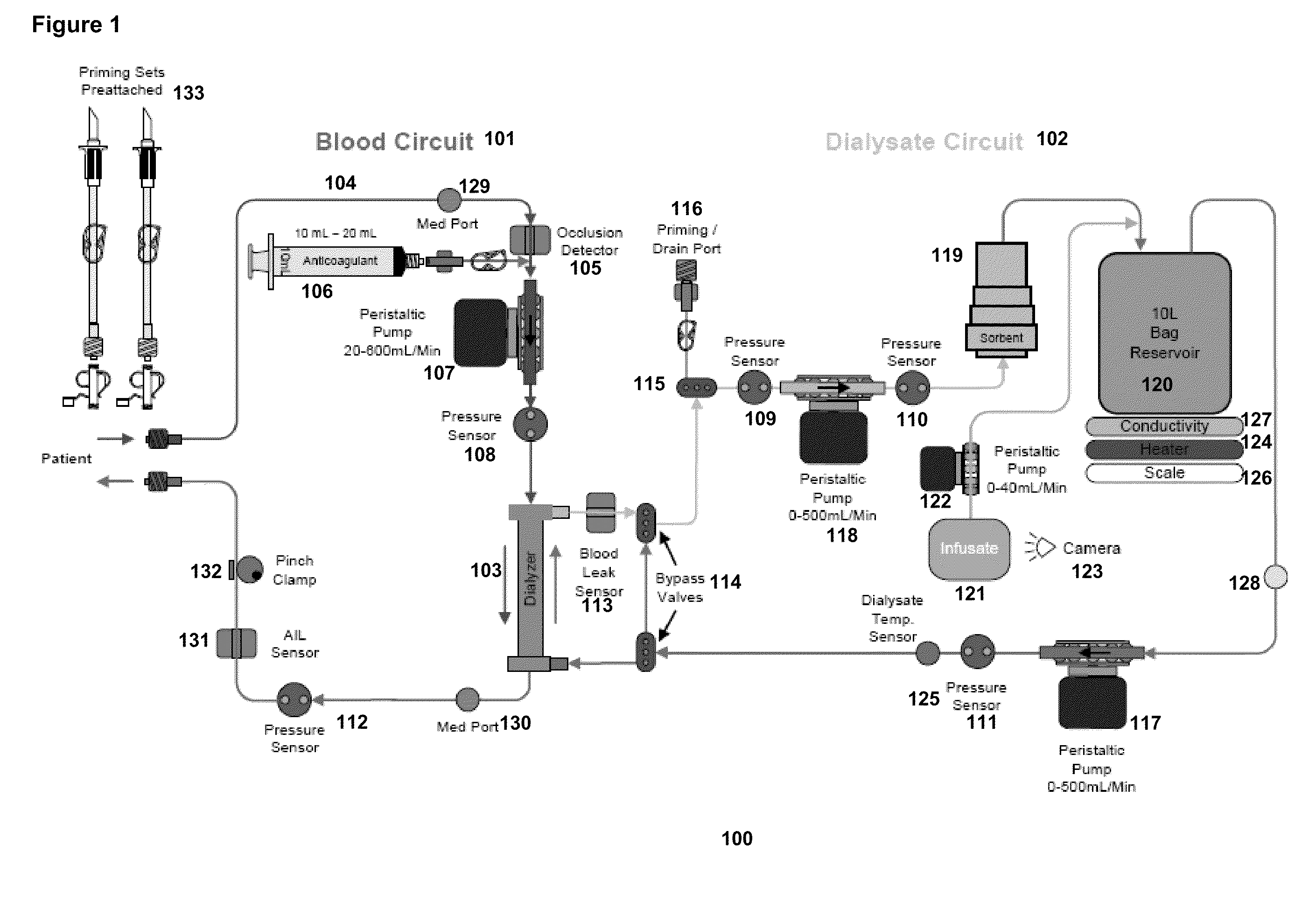
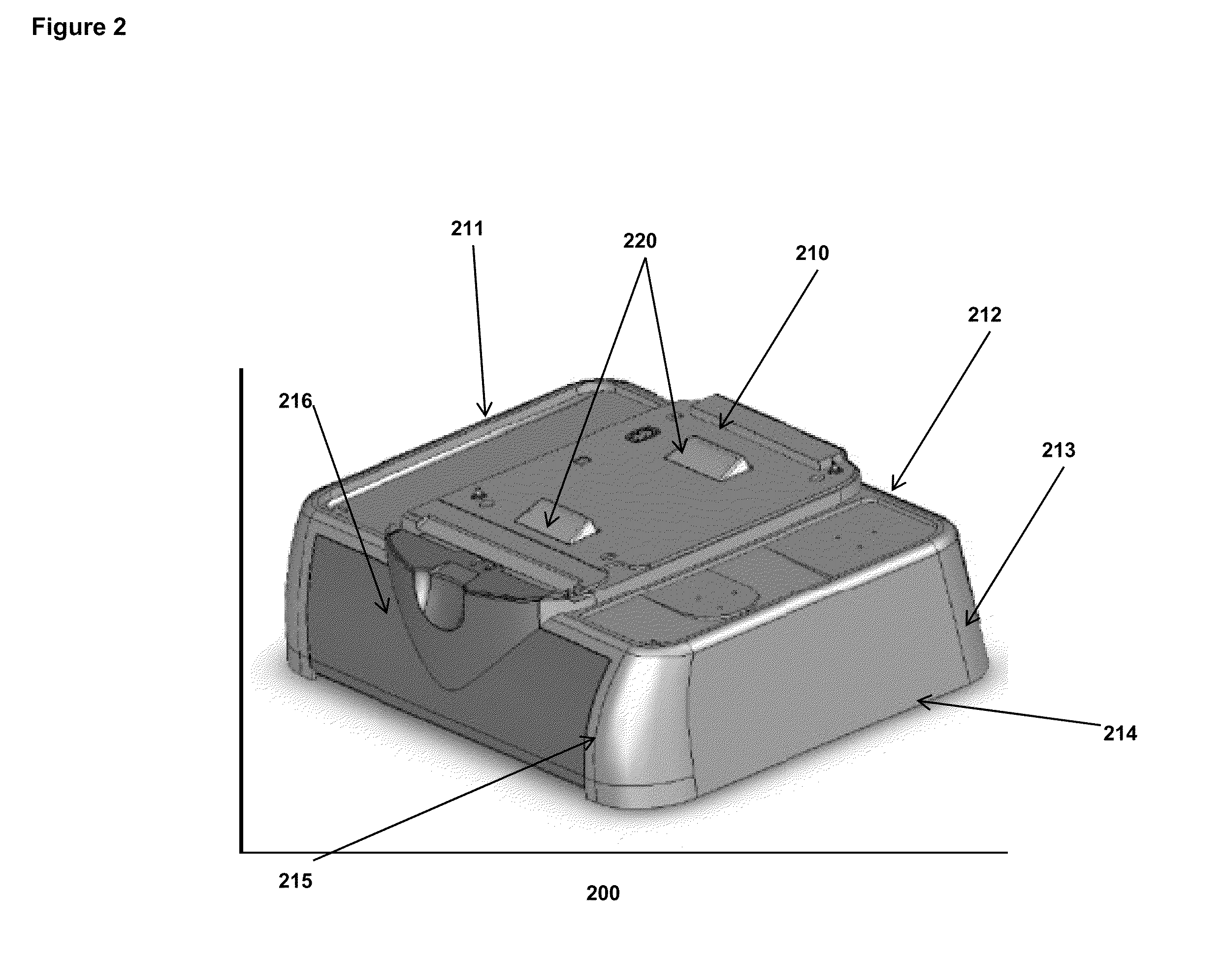
[0021]The present invention is directed towards a dialysis unit that is modular and portable, and capable of operating with hemodialysis as well as hemofiltration protocols. In one embodiment, one of the main functional modules of the modularized dialysis system is built around the dialysate reservoir and integrates the reservoir with the reservoir...


PUM


Abstract

The present specification discloses a dialysis system having a reservoir module with a reservoir housing defining an internal space, a surface located within the internal space for supporting a container that contains dialysate, and a conductivity sensor located within the internal space, where the conductivity sensor has a coil, a capacitor in electrical communication with the coil, and an energy source in electrical communication with the circuit.

Description

CROSS-REFERENCE[0001]The present invention relies on U.S. Patent Provisional No. 61 / 165,389, filed on Mar. 31, 2009, for priority. The present invention is also a continuation-in-part of U.S. patent application Ser. No. 12 / 610,032, filed on Oct. 30, 2009, which relies on U.S. Provisional Application No. 61 / 109,834, filed on Oct. 30, 2008. The present invention is also related to a) U.S. patent application Ser. No. 12 / 575,450, filed on Oct. 7, 2009, b) U.S. patent application Ser. No. 12 / 575,449, filed on Oct. 7, 2009, c) U.S. patent application Ser. No. 12 / 355,102, filed on Jan. 16, 2009, d) U.S. patent application Ser. No. 12 / 355,128, filed on Jan. 16, 2009, e) U.S. patent application Ser. No. 12 / 351,969, filed on Jan. 12, 2009, f) U.S. patent application Ser. No. 12 / 324,924, filed on Nov. 28, 2008, g) U.S. patent application Ser. No. 12 / 210,080, filed on Sep. 12, 2008, h) U.S. patent application Ser. No. 12 / 238,055, filed on Sep. 25, 2008, i) U.S. patent application Ser. No. 12 / 23...

Claims


Application Information

Patent Timeline
IPC IPC(8): B01D61/32
CPCA61M1/1656A61M2205/3317A61M1/1664A61M2209/084A61M1/166A61M2205/3393A61M1/16A61M2205/3306A61M2205/3368A61M1/1666A61M1/1668A61M1/167A61M1/3403A61M1/34A61M2205/15G01N33/48707A61M1/1621A61M2205/36G01N27/221G01N27/228
Inventor FULKERSON, BARRY N.SMITH, MARK F.
Owner FRESENIUS MEDICAL CARE HLDG INC
Learn More