Organic electroluminescent device and display apparatus

a technology of electroluminescent devices and display devices, which is applied in the direction of basic electric elements, electrical devices, and semiconductor devices, can solve the problems of reducing luminous efficiency and increasing voltage, and achieves high electron injection properties, reduced electron injection barriers, and high electron injection barriers

Active Publication Date: 2010-10-07
JOLED INC
View PDF14 Cites 24 Cited by
  • Summary
  • Abstract
  • Description
  • Claims
  • Application Information

AI Technical Summary

Benefits of technology

[0011]In the organic electroluminescent device and display apparatus having the above structure, the electron transport layer has a stacked structure, and the layer containing the benzimidazole derivative is provided on the cathode side of the layer containing the dibenzimidazole derivative represented by general formula (1). When only the dibenzimidazole derivative represented by general formula (1) is used, the electron injection barrier from the cathode is high. However, the electron injection barrier can be reduced by stacking a benzimidazole derivative having a high electron injection property on the cathode side. When only such a benzimidazole derivative is used, electrons are excessively supplied to a light-emitting layer. However, the amount of electrons can be adjusted by stacking the dibenzimidazole derivat

Problems solved by technology

As a result, an increase in the voltage and a decrease in

Method used


Image

  • Organic electroluminescent device and display apparatus
  • Organic electroluminescent device and display apparatus
  • Organic electroluminescent device and display apparatus

Examples


application examples

9. Application Examples

[0112]The above-described display apparatus according to an embodiment of the present invention can be applied to a display apparatus of electronic equipment in various fields which display, as a picture image or video image, video signals input to the electronic equipment or video signals generated in the electronic equipment, such as various types of electronic equipment shown in FIGS. 4 to 8G, for example, digital cameras, notebook-type personal computers, mobile terminal apparatuses such as mobile phones, and video cameras. Examples of electronic equipment to which an embodiment of the present invention in applied will be described below.

[0113]FIG. 4 is a perspective view showing a television to which an embodiment of the present invention is applied. The television according to this application example includes an image display screen 101 composed of a front panel 102, a filter glass 103, etc., and can be produced by using the display apparatus according ...

examples

[0118]Next, a description will be made of methods of producing organic electroluminescent devices of specific Examples of the present invention and Comparative Examples to these Examples and evaluation results of the organic electroluminescent devices.

examples 1 to 8

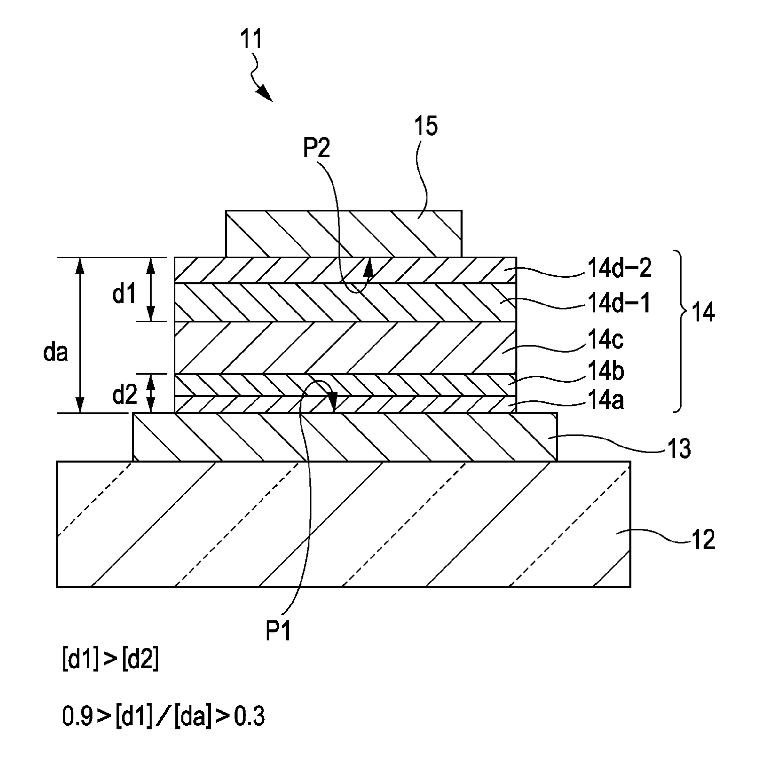
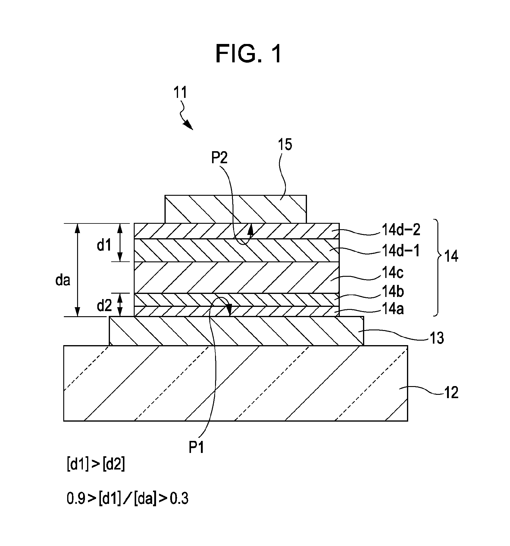
[0119]The organic electroluminescent devices 11 having the structure described with reference to FIG. 1 in the above embodiment were prepared. Each of the organic electroluminescent devices 11 was formed as a top-emission type organic electroluminescent device 11 in which light emitted when holes injected from the anode 13 and electrons injected from the cathode 15 are recombined in the light-emitting layer 14c is extracted from the cathode 15 side. In addition, each of the organic electroluminescent devices 11 was formed as a resonator structure in which emitted light is resonated between the anode 13 and the cathode 15 and is extracted. Table 27 shows the layer structures of Examples 1 to 8 together with those of Comparative Examples 1 to 5. However, a description of structures common to the Examples and Comparative Examples is omitted. Methods of producing the organic electroluminescent devices 11 will be described below.

TABLE 27First electronSecond electronCurrentHole injectionH...


PUM


Abstract

An organic electroluminescent device includes an anode; a cathode; an organic layer including a light-emitting layer and disposed between the anode and the cathode; and an electron transport layer constituting the organic layer, disposed between the cathode and the light-emitting layer, and having a stacked structure including a layer containing a benzimidazole derivative and a layer containing a dibenzimidazole derivative represented by general formula (1):
wherein Y1 to Y8 each represent a substituted or unsubstituted aryl group having 6 to 60 carbon atoms, a substituted or unsubstituted alkenyl group, a substituted or unsubstituted pyridyl group, a substituted or unsubstituted quinolyl group, a substituted or unsubstituted alkyl group having 1 to 20 carbon atoms, a substituted or unsubstituted alkoxy group having 1 to 20 carbon atoms, or a substituted or unsubstituted aliphatic cyclic group, and Y7 and Y8 may form a ring through a linking group.

Description

BACKGROUND OF THE INVENTION[0001]1. Field of the Invention[0002]The present invention relates to an organic electroluminescent device (organic EL device) and a display apparatus. In particular, the present invention relates to an organic electroluminescent device and a display apparatus that include an electron transport layer containing a nitrogen-containing heterocyclic derivative.[0003]2. Description of the Related Art[0004]Organic electroluminescent devices (organic EL devices) that use electroluminescence (hereinafter abbreviated as EL) of organic materials include an anode, a cathode, and an organic layer including a light-emitting layer and disposed between the anode and the cathode, and are attracting attention as light-emitting devices that can emit light with high luminance by a low-voltage direct current drive.[0005]In organic electroluminescent devices having such a structure, various studies have been made on the layer structure between the anode and the cathode and con...

Claims


Application Information

Patent Timeline
IPC IPC(8): H01L51/54
CPCH10K59/12H10K85/633H10K85/631H10K85/6572H10K50/14H10K2102/351
Inventor KAMBE, EMIKOKIJIMA, YASUNORI
Owner JOLED INC
Why Eureka
Try Eureka