
Method and devices for driving a damper

a damper and damping technology, applied in the direction of dynamo-electric converter control, motor/generator/converter stopper, program control, etc., can solve the problems of increasing torque, damage to gear trains, electrical motors, etc., and achieve the effect of reducing drive current and avoiding damage to electrical motors and/or gear trains

Active Publication Date: 2010-10-07
BELIMO HOLDING AG
View PDF14 Cites 21 Cited by
  • Summary
  • Abstract
  • Description
  • Claims
  • Application Information

AI Technical Summary

Benefits of technology

[0006]According to the present invention, the above-mentioned objects are particularly achieved in that the control module of the actuator or a separate control device for the actuator is further configured to reduce the drive current to a lower level, for maintaining the damper in the second position when a defined duration of time has elapsed since activation of the actuator. Thus, the control module makes it possible to reduce the drive current to a lower level for maintaining the damper in the second position against the bias force, when a defined current reduction time has elapsed since activation of the actuator. Thereby, damages to the electrical motor and / or gear trains can be avoided without having to detect an increased drive current, because the drive current is reduced solely based on a fixed time duration, without any circuitry or sensory equipment for measuring the drive current. For example, for flexible configuration, the value of the defined current reduction time is stored in a data store.

Problems solved by technology

An increase of the drive current provided to the electrical motor in the stalled position produces an increased torque that may damage the gear train and over time overheat the motor.
Nevertheless, the circuitry needed for detecting an increased drive current and possibly rotation of the electrical motor adds complexity and costs to the manufacture of an actuator.

Method used


Image

  • Method and devices for driving a damper
  • Method and devices for driving a damper
  • Method and devices for driving a damper

Examples


Embodiment Construction

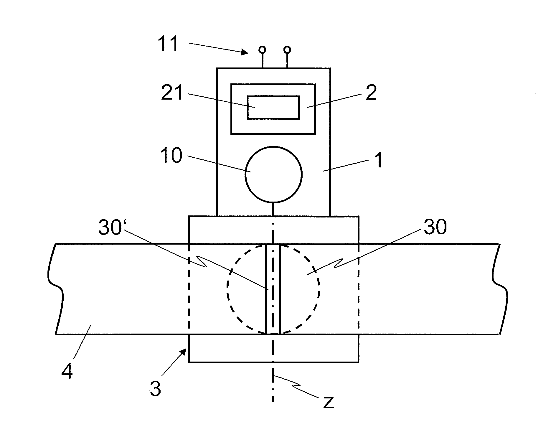
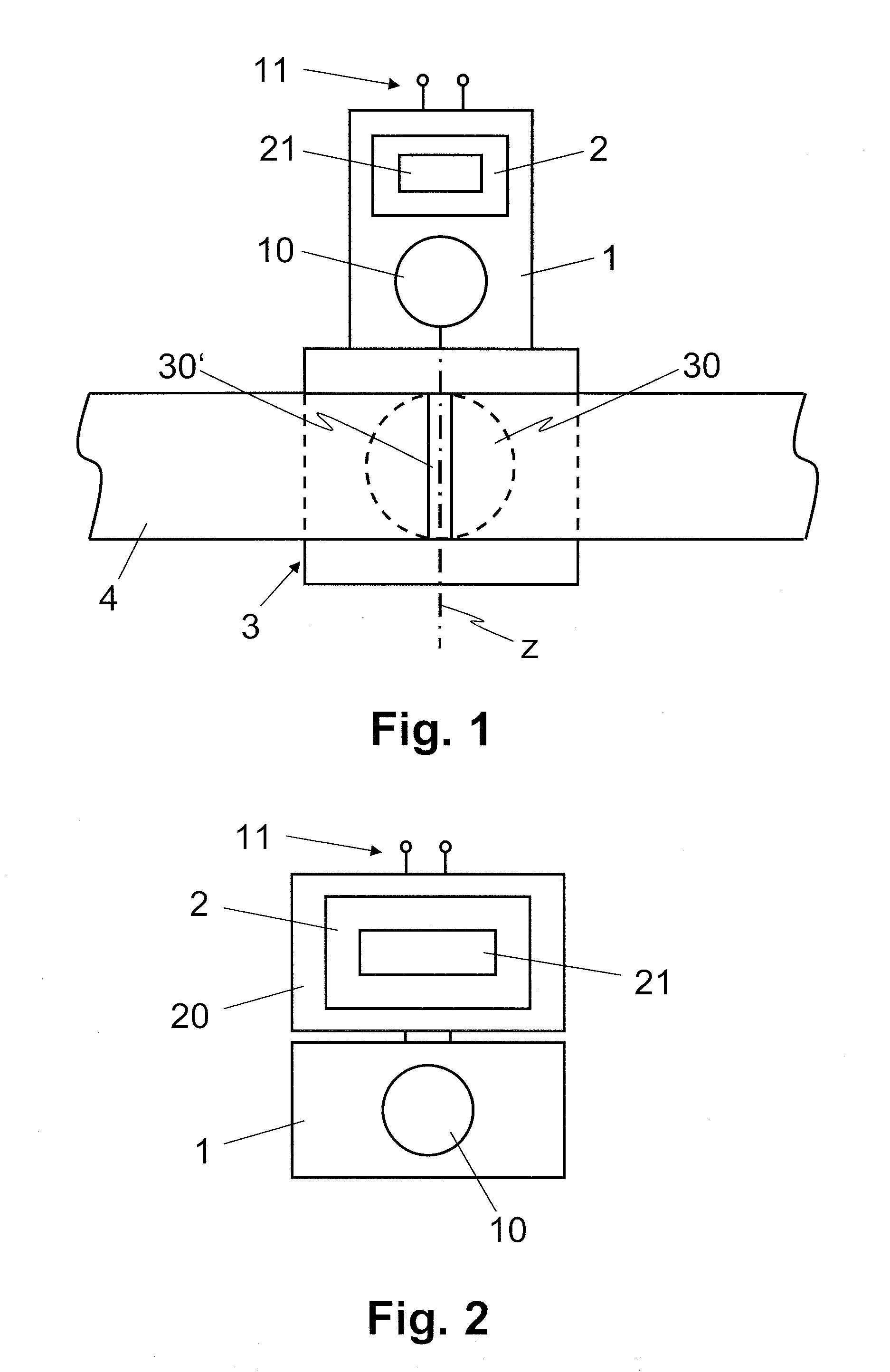
[0013]In FIG. 1, reference numeral 3 refers to a damper arranged in a fluid conduit 4, e.g. an air duct, a water pipe or a gas pipe. For example, the damper 3 is configured as a fire protection flap. In FIG. 1 reference numeral 30 refers to the damper 3 in a first (open) position; reference numeral 30′ refers to the damper 3 in a second (closed) position. The damper 3 is biased toward the first (open) position with at least one spring (not illustrated). Although in FIG. 1, the first and second positions are illustrated as open and closed positions, respectively, one skilled in the art will understand that in an alternative application / implementation, the first position is the closed position whereas the second position is the open position.

[0014]In FIGS. 1 and 2, reference numeral 1 refers to an actuator comprising an electrical motor 10 which is operatively coupled to the damper 3, for driving the damper 3, against the bias force produced by the spring, from the first (rest) positi...


PUM


Abstract

An actuator (1) comprises an electrical motor (10) for driving a damper (3) from a rest position to a stalled position. The damper (3) is biased toward the rest position with at least one spring. A control module (2) is configured to supply, upon activation of the actuator (1), a drive current to the electrical motor (10) for driving the damper (3) from the rest position to the stalled position against a bias force produced by the spring. The control module (2) is further configured to reduce the drive current to a lower level for maintaining the damper (3) in the stalled position when a defined duration of time has elapsed since activation of the actuator (1). Damages to the electrical motor (10) and / or gear trains can be avoided without having to provide any circuitry or sensory equipment for measuring the drive current.

Description

FIELD OF THE INVENTION [0001]The present invention relates to a method and devices for driving a damper. Specifically, the present invention relates to a method and devices for operating an actuator including an electrical motor to drive a damper from a rest position to a stalled position. More specifically, the present invention relates to a method, an actuator, and a control device for operating an actuator including an electrical motor to drive the damper which is biased toward the rest position with at least one spring.BACKGROUND OF THE INVENTION[0002]Particularly in HVAC applications (Heating, Ventilating, and Air Conditioning) for climate control in residential, commercial and public buildings, actuators with electrical motors are used to drive dampers in air ducts. The dampers are biased toward a rest position by one or more springs which produce a bias force toward the rest position. Upon activation, i.e. when the actuator or the electrical motor, respectively, is turned on,...

Claims


Application Information

Patent Timeline
IPC IPC(8): H02P7/28
CPCG05B2219/37622G05B19/402
Inventor KUSTER, BEATBEARTH, ROY
Owner BELIMO HOLDING AG
Learn More