Upconverter

Active Publication Date: 2010-10-07
SIEMENS HEALTHCARE GMBH
View PDF16 Cites 15 Cited by
  • Summary
  • Abstract
  • Description
  • Claims
  • Application Information

AI Technical Summary

Benefits of technology

[0009]A local oscillator signal received by the antenna is input to the power splitter and the power splitter then provides a portion of the received local oscillator signal to

Problems solved by technology

These add cost and inconvenience to the structure.
In use, the requirement to connect the cables and sterilise them between scanning one patient and the next leads to down-time between scans.
However, wireless implementations give rise to new problems.
The resulting low impedance presented to the local os

Method used


Image

  • Upconverter
  • Upconverter
  • Upconverter

Examples


Example

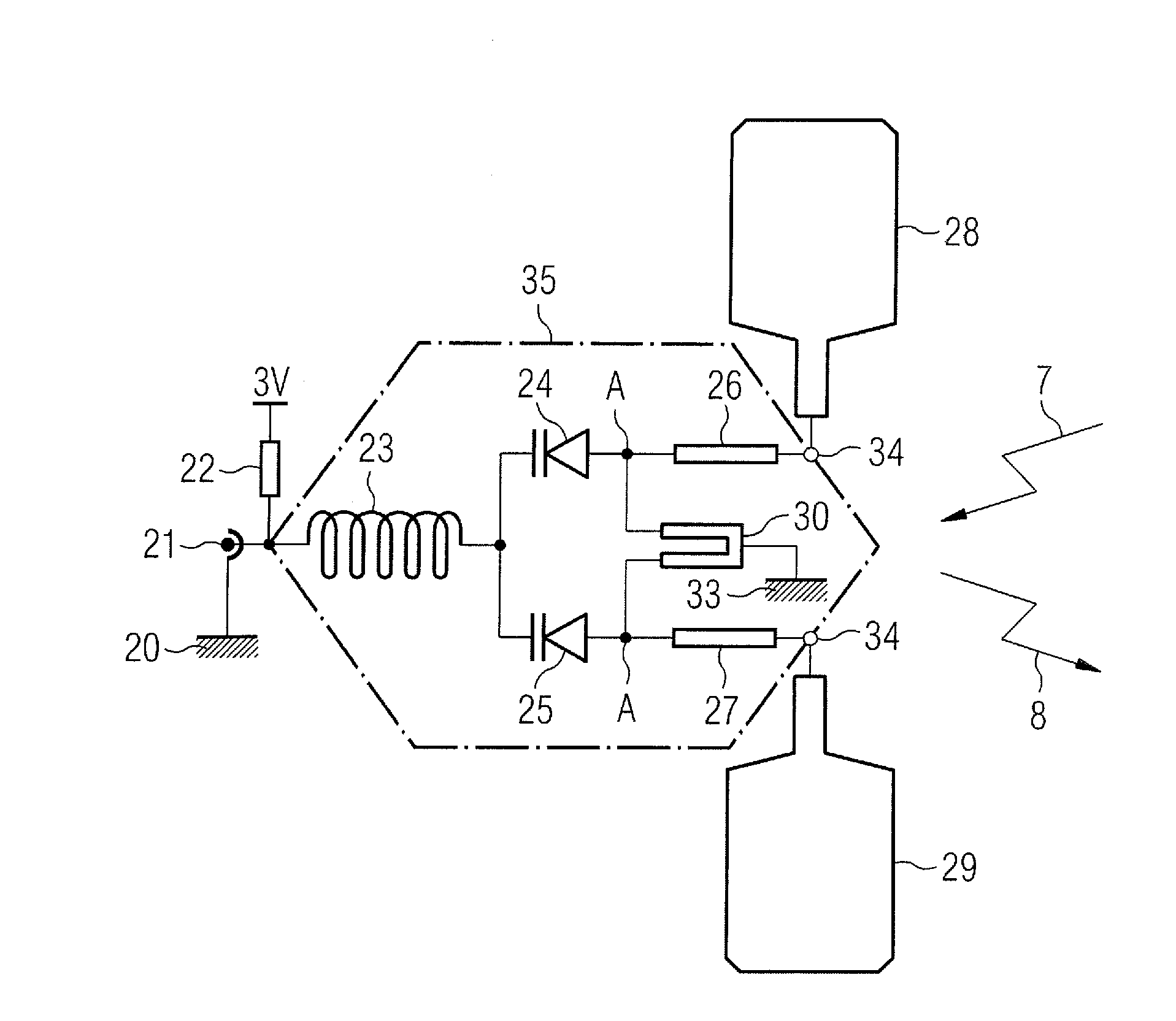
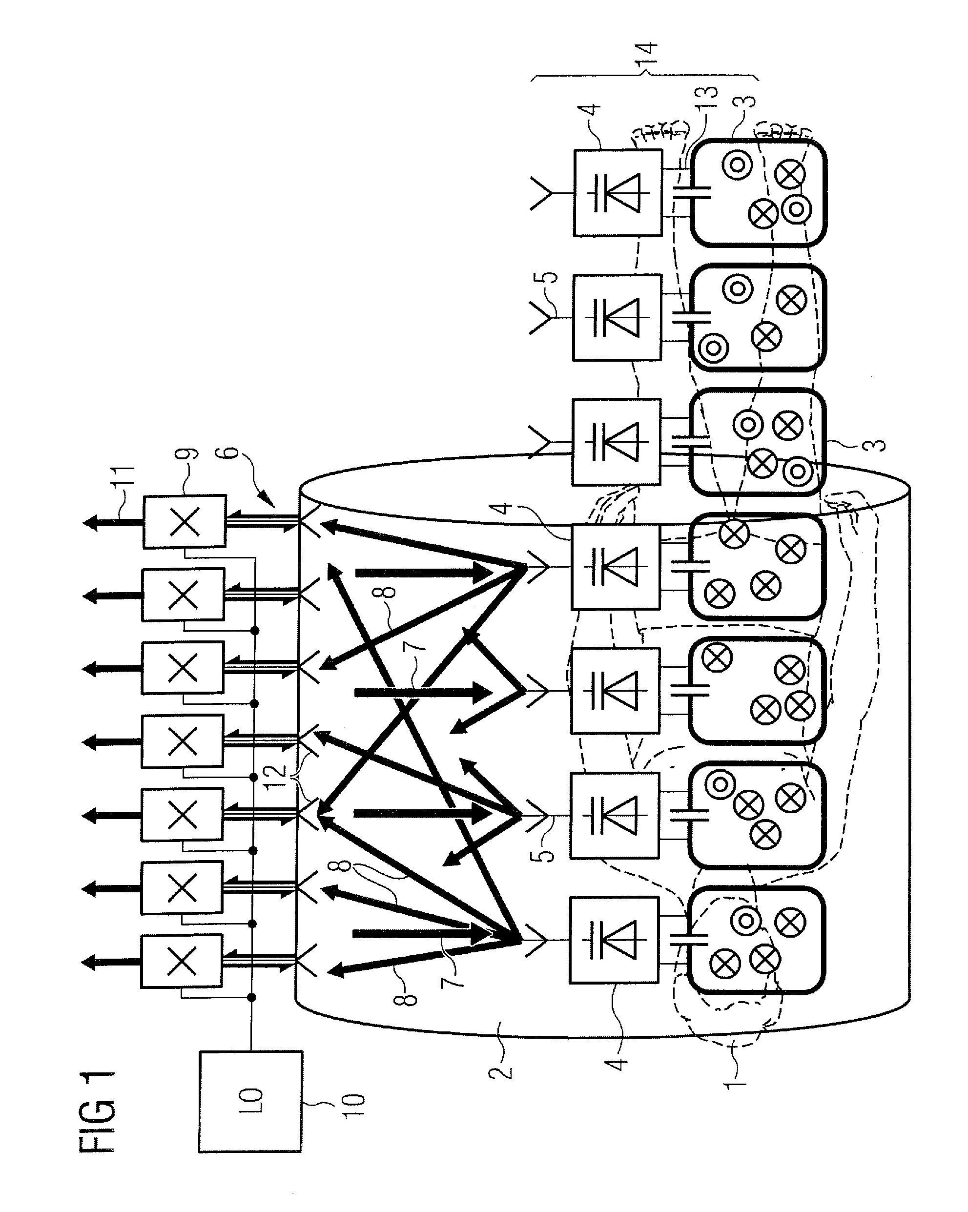
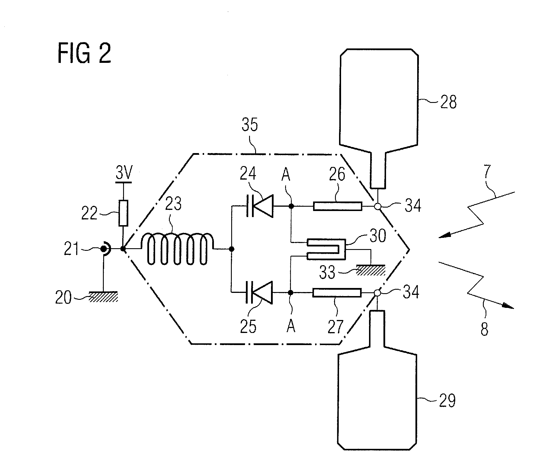
[0032]The wireless concept to which the features of the present invention apply is based on upconversion, in the patient mat, of the RF (Larmor) frequency signals from the patient coils to microwave frequencies for transmission to microwave antennas located on the bore of the scanner. The combination of transmit and receive antennas on the patient and bore respectively constitutes a MIMO (Multiple Input / Multiple Output) system. The greater multiplicity of receive antennas in the bore array allows individual signals from a number of patient antennas to be resolved. The present invention relates to an implementation of the upconversion process.

[0033]An example of an MRI system using a MIMO microwave link, for example as described in more detail in the aforementioned co-pending UK patent application no. 0903722.7 corresponding to U.S. Ser. No. 12 / 612,831, is shown in FIGS. 1 and 2. FIG. 1 shows a patient 1 within an MRI scanner bore tube 2. A mat covers part of the patient for imaging ...


PUM


Abstract

An upconverter has a two port parametric amplifier that has a first port to receive an input, signal to be amplified and upconverted and a second port to receive a local oscillator signal and to output the amplified, upconverted signal at upper and lower sideband frequencies. The upconverter further has an antenna coupled to the second port and a power splitter inserted between the second port of the parametric amplifier and the antenna.

Description

BACKGROUND OF THE INVENTION[0001]1. Field of the Invention[0002]The present invention relates to an upconverter using a two port parametric amplifier, in particular for use in magnetic resonance imaging (MRI) systems.[0003]2. Description of the Prior Art and Related Subject Matter[0004]MRI scanners use a combination of a strong constant magnetic field (B0) from a superconducting magnet which is modified by gradient fields generated by gradient coils, together with a rotating magnetic field (B1) from a radio frequency (RF) antenna to excite nuclear magnetic resonances in the body that generate short term RF signals that are received to build up a tomographic image.[0005]All current-generation MRI scanners employ arrays of local coils mounted in close proximity to the scanned patient to receive the RF with maximum possible signal to noise ratio (SNR). The local coils that receive signals from the back of the patient are mounted in the patient table. Local coils that receive signals fr...

Claims


Application Information

Patent Timeline
IPC IPC(8): G01R33/20G06G7/12
CPCG01R33/3415H03F7/04G01R33/3692G01R33/3621G01R33/36
Inventor VESTER, MARCUS
Owner SIEMENS HEALTHCARE GMBH
Why Eureka
Try Eureka