

Variable inductor
- Summary
- Abstract
- Description
- Claims
- Application Information
AI Technical Summary
Problems solved by technology
Method used
Image

Examples
Embodiment Construction
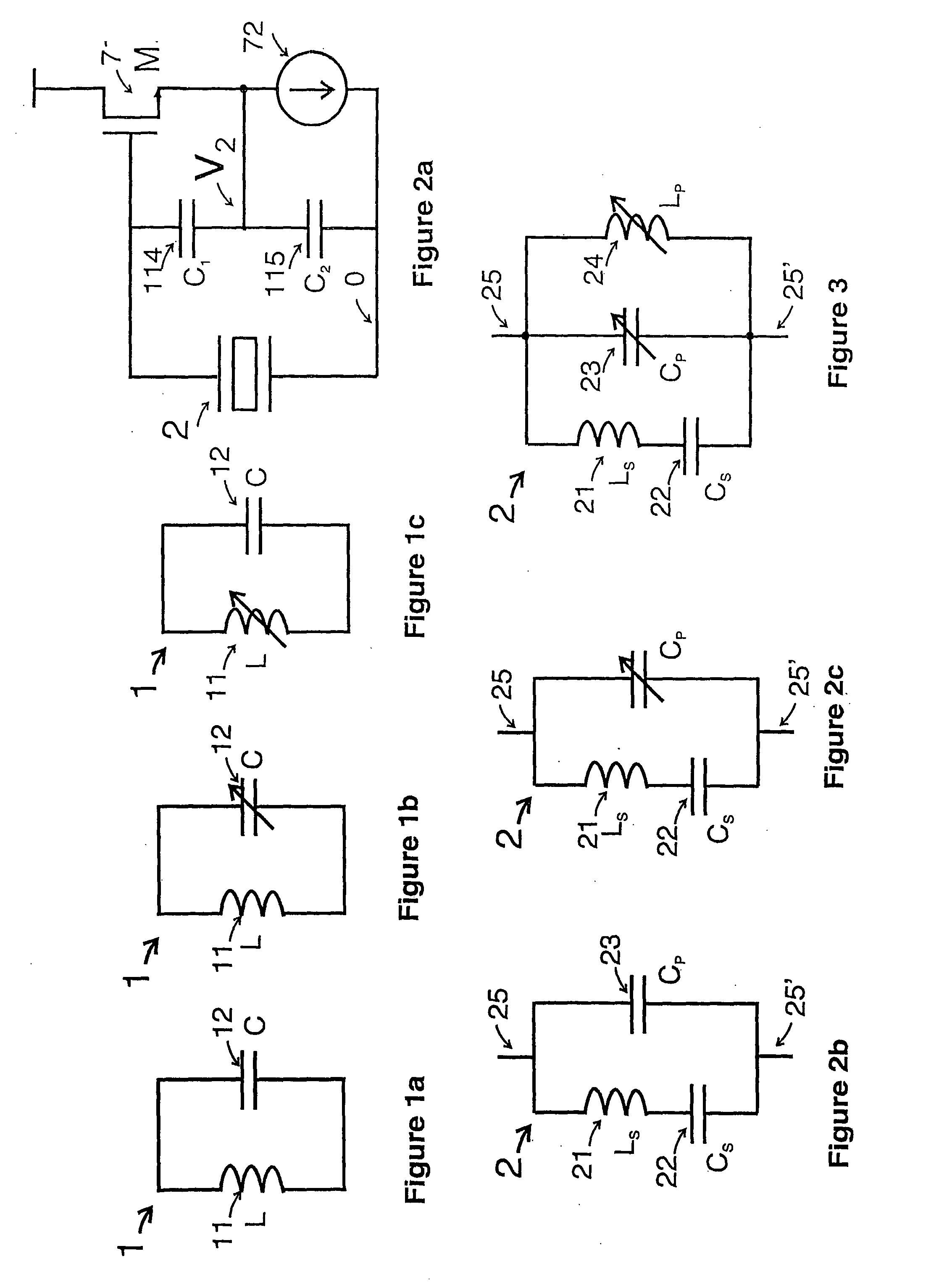
[0034]The circuit of FIG. 3 is a modified form of the resonator circuit shown in FIG. 2c in accordance with the first aspect of the invention. A variable inductor Lp is connected in parallel to Cp. The admittance of the resulting combination is given by equation (2) when it is
Yp=j2πfpCp+1j2πfpLp=j2πfp(Cp-1(2πfp)2Lp)=j2πfpCp′(2)
at or close to the resonant frequency fp. As long as Cp′ is positive the combined impedance is capacitive, with the equivalent capacitance Cp′ smaller than Cp. When used in a VCXO the smaller equivalent parallel capacitance thus created extends the tuning range of the VCXO.
[0035]In FIG. 3 the capacitance Cp is shown as a variable capacitance and, as explained above in relation to FIG. 2c, it comprises the case capacitance of the crystal 2 and an external variable capacitor connected in parallel. The external variable capacitor can be omitted or made fixed, leaving the tuning to the variable inductor 24, but this of course will reduce the range of tuning availa...
PUM
 Abstract
Description
Claims
Application Information