DC to AC inverter

Active Publication Date: 2010-10-07
ABLEREX ELECTRONICS CO LTD
View PDF6 Cites 16 Cited by
  • Summary
  • Abstract
  • Description
  • Claims
  • Application Information

AI Technical Summary

Benefits of technology

[0017]The buck converter and the buck/boost converter operate alternately to generate an AC sinusoidal current, which is output by the AC output port to inject into the single-phase utility system. The buck converter produces the positive half-cycle signal of the AC sinusoidal current when the single-phase utility system is in positive half cycle. The buck/boost converter produces the negative half-cycle signal of the AC sinusoidal current when the single-phase uti

Problems solved by technology

The wide use of fossil fuels has resulted in the problem of greenhouse emissions worldwide, which has also seriously damaged the earth's environment.
Moreover, fossil fuels will be exhausted in the future, and the cost of fossil fuels has signif

Method used


Image

  • DC to AC inverter
  • DC to AC inverter
  • DC to AC inverter

Examples


first embodiment

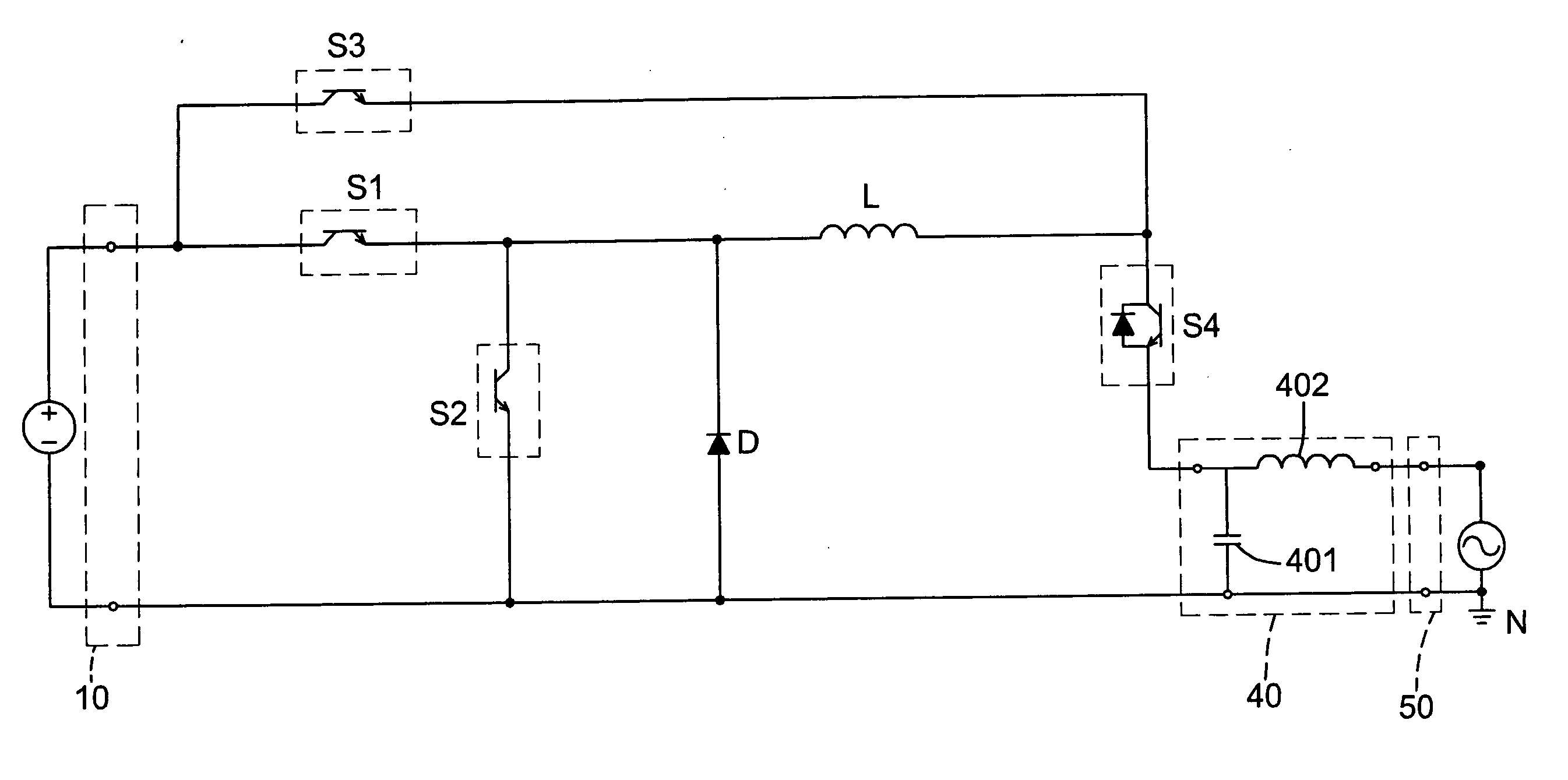
[0035]With reference to FIG. 4, in the DC to AC inverter, the buck converting circuit of the buck converter (20) and the buck / boost converting circuit of the buck / boost converter (30) commonly comprise first to fourth power electronic switches (S1)-(S4), a diode (D), and an energy storage inductor (L). The first power electronic switch (S1), the second power electronic switch (S2), and the third power electronic switch (S3) are made of power electronic switches. The fourth power electronic switch (S4) is configured by connecting a power electronic switch and a diode in parallel. The energy storage inductor (L) is shared by the buck converter (20) and the buck / boost converter (30).

[0036]A first end of the first power electronic switch (S1) is connected to the positive input terminal of the DC power input port (10), and a second end thereof is connected to a first end of the second power electronic switch (S2). A second end of the second power electronic switch (S2) and the first end ...

second embodiment

[0042]With reference to FIG. 6, the DC to AC inverter is shown. The buck converting circuit of the buck converter (20) and the buck / boost converting circuit of the buck / boost converter (30) comprise first to fourth power electronic switches (S1)-(S4), a first energy storage inductor (L1), and a second energy storage inductor (L2). In particular, each of the second power electronic switch (S2) and the fourth power electronic switch (S4) is formed by a power electronic switch and a diode in series.

[0043]A first end of the first power electronic switch (S1) is connected to the positive input terminal of the DC power input port (10). A second end of the first power electronic switch (S1) is connected to a second end of the fourth power electronic switch (S4) and the first end of the first energy storage inductor (L1). The first end of the fourth power electronic switch (S4) is connected to the negative input terminal of the DC power input port (10). A first end of the third power electr...


PUM


Abstract

A DC to AC inverter has a DC power input port, a buck converter, a buck/boost converter, an output filter and an AC output port. The DC power input port has a positive input terminal and a negative input terminal, both connected to a DC source. The AC output port is connected to a single-phase utility system. When the single-phase utility system is in positive half cycle, the buck converter generates a positive half-cycle signal of sinusoidal current. When the single-phase utility system is in negative half cycle, the buck/boost converter generates a negative half-cycle signal of sinusoidal current. In either the positive or negative half cycles, only one power electronic switch is switched in high frequency to reduce switching loss. Further, the negative input terminal of the DC power input port of the invention can be connected to a neutral line of the single-phase utility system.

Description

BACKGROUND OF THE INVENTION[0001]1. Field of the Invention[0002]The invention relates to a DC to AC inverter and, in particular, to a DC to AC inverter that can reduce switching loss and increase system efficiency and a negative input terminal of a DC power input port can be directly connected to the neutral line of a single-phase utility system.[0003]2. Description of Related Art[0004]The wide use of fossil fuels has resulted in the problem of greenhouse emissions worldwide, which has also seriously damaged the earth's environment. Moreover, fossil fuels will be exhausted in the future, and the cost of fossil fuels has significantly increased recently. Governments worldwide expect to develop renewable energy to alleviate the above problems. Therefore, it has become a trend to look for green energy in place of fossil energy. This results in the interest in developing solar power, wind power, and fuel cells. The grid-connected solar power system and wind power system are the importan...

Claims


Application Information

Patent Timeline
IPC IPC(8): H02M1/12
CPCH02M7/537
Inventor WU, CHIN-CHANGCHEN, CHUN-HANKAO, MING-SHENGLAI, LI-HSIANGFENG, YA-TSUNG
Owner ABLEREX ELECTRONICS CO LTD
Why Eureka
Try Eureka