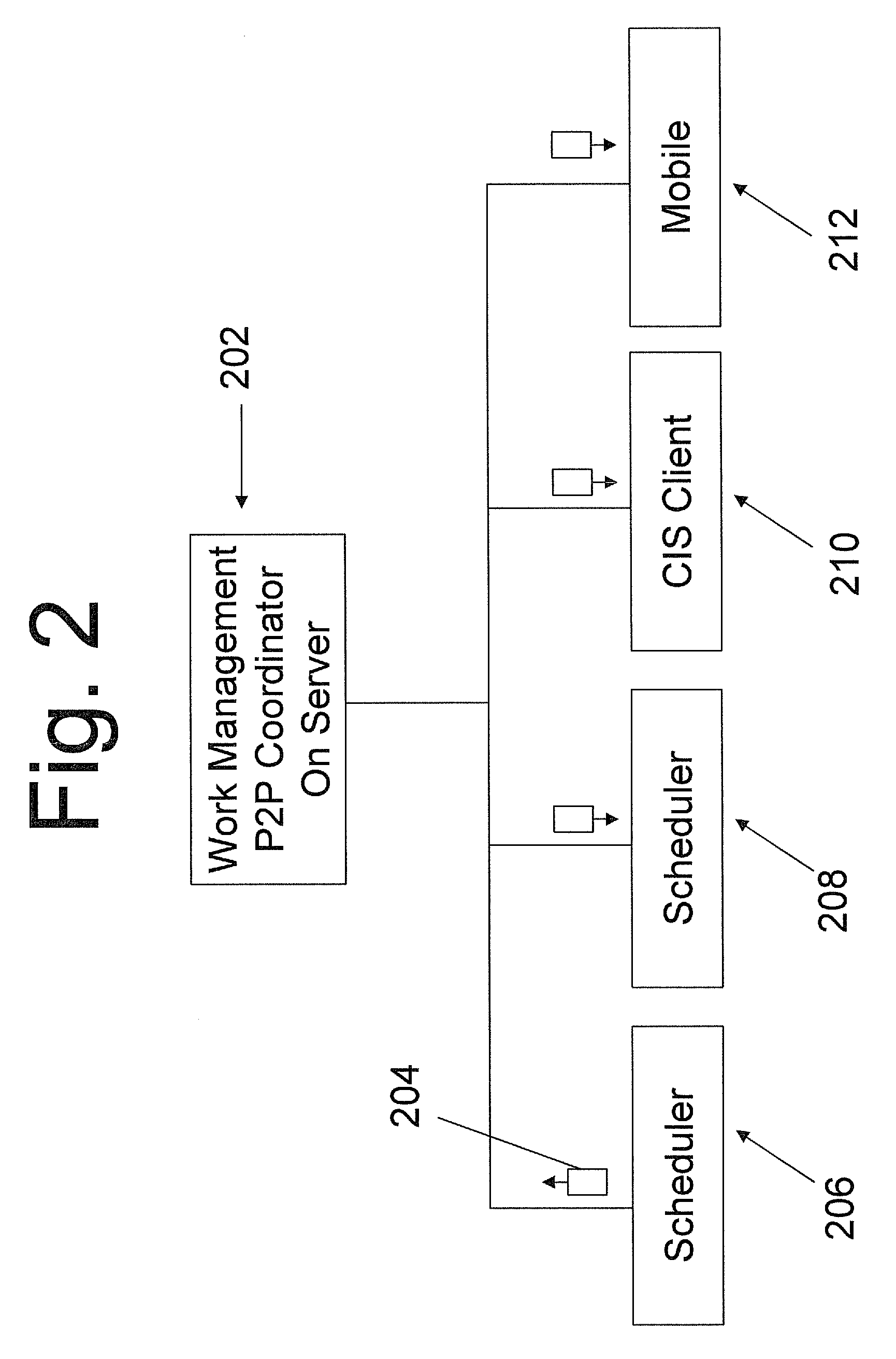
[0013]The invention is a computer implemented system and method that ties in complex calendar event relationships, which provides the user with a context and view of how a task needs to be completed and how it relates to larger initiatives and resources available. The system and method supports next to real time notification methods using a peer-to-peer (p2p) type messaging architecture. As with other p2p architecture type computer networks, the present invention can use diverse
connectivity between participants in a network to thereby utilize the cumulative bandwidth of network participants rather than conventional centralized resources where a relatively low number of servers provide the core value to a service or application. As with other p2p networks, the p2p network of the present invention can be used for connecting nodes via largely ad hoc connections. Such networks are useful for many purposes including providing next to real
time information updates to each of the participants.
[0017]One aspect of the present invention is a
graphical user interface tying into a Work Management engine, where the
graphical user interface provides a view to the user that reveals current status of assigned tasks, resource availability and allocation, task
queue and calendar of events. Users can see the entire
Workflow right from the scheduling screen. This unique integration with the calendar allows the user to see how their calendar task relates to the Work Management
Server. Additional task information can be seen from the Work Management
Server as well that has little to do with Scheduling. Individual workloads can easily be calculated from the work
queue in a graphical manner. This top level view gives dispatchers a quick view of which resources are under utilized and need more work and how much work the entire group is scheduled for. Individual schedules can be observed while tasks are selected and slotted based on first availability. After a task is selected from the work queue, the first available button can be pushed to find the next available time slot based on Work Group and personal schedules. First available calculations are based on Normal Work Schedules, Time off, and meetings.
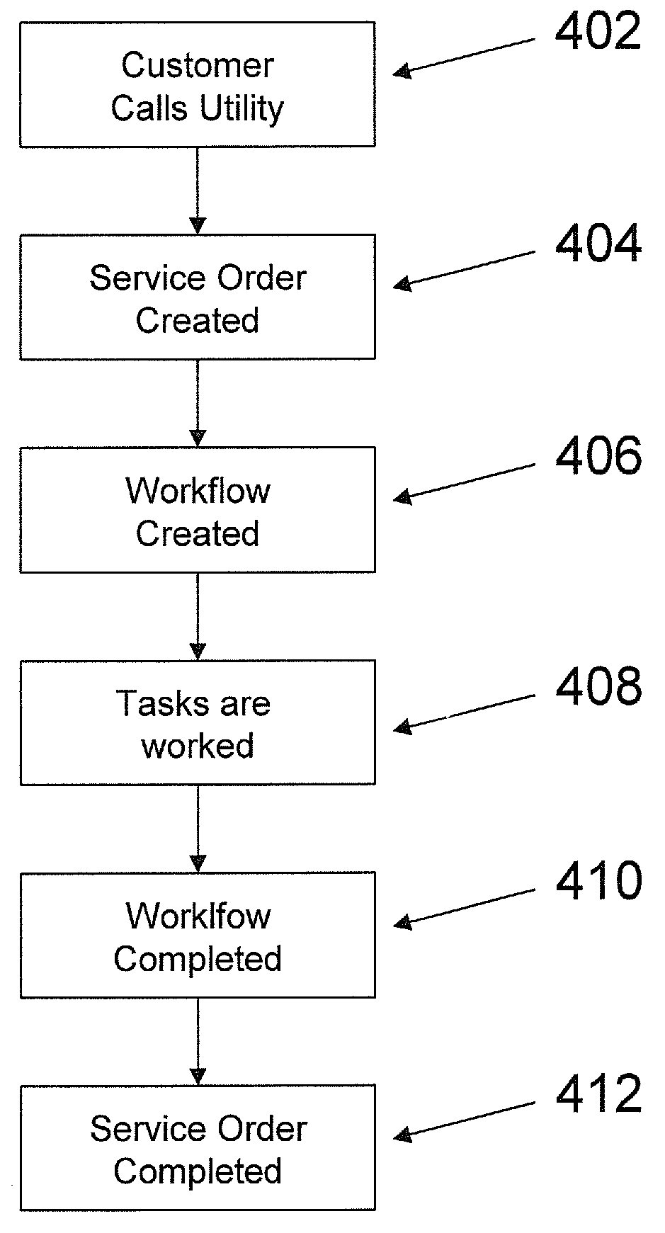
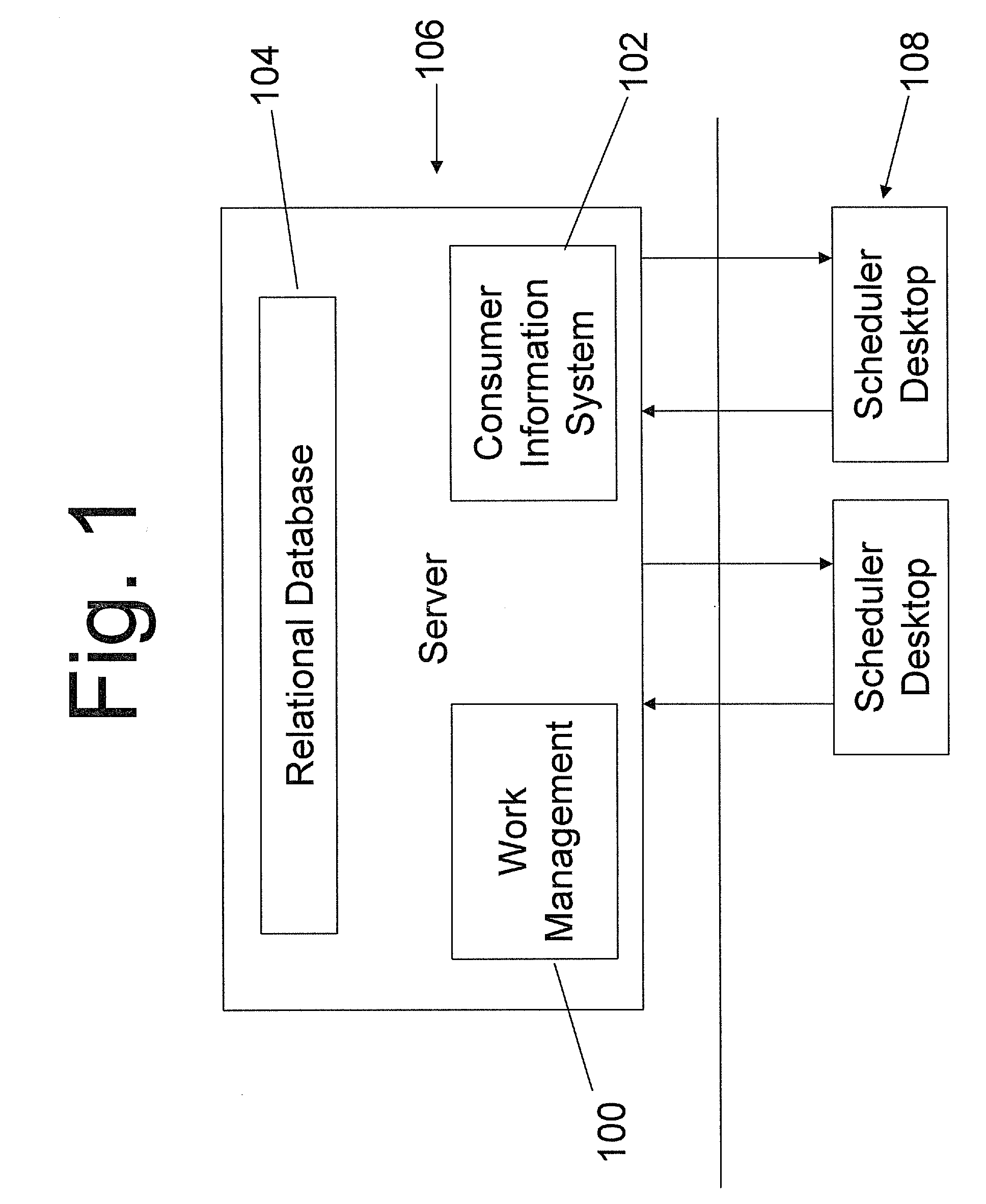
[0018]Service Orders can be created by customer service representatives. These service orders can then be interpreted by the Work
Management system to determine “what” and a series of tasks is created in a
workflow based on the “what” that describes “how”, “when” and “who”. These tasks will contain specific ordering and can be routed to default workgroups that typically perform the work defined in the task. These tasks can then be assigned and scheduled to individuals or crews at strategic points in time. The tasks within a
work flow may all be assigned to an individual
workgroup or subdivided and assigned to multiple workgroups based on expertise or
workload. These assignments and scheduling functions are made by the Graphical Resource Scheduler and can be consumed by downstream task consuming applications such as Mobile Workforce, Outage Management or
Staking. Graphical Resource Scheduler can provide filtering capabilities that help dispatchers
restrict the work in view so that volume does not impede the user's ability to efficiently schedule work.
[0019]The User can utilized the
drag and drop experience for scheduling tasks and booking resources from the work
management system. The present invention provides the ability to drag resources or tasks onto each other graphically to dynamically initiate and affect the assignment and scheduling status of a task. A user can click on and select on of the tasks listed in queue and drag the task from the queue window to the calendar area of the screen depicting the calendar for a group and can drop the task at the appropriate case on the calendar, then expand the task to the appropriate duration. A resource can then be selected by clicking on it and dragging it over to the calendar section of the display and releasing over the previously scheduled task. The task has now been assigned. This graphical
drag and drop interaction with the
user interface can automatically initiate the passing of a data packet to the work
management system, which can be translated into a scheduling and notification event, where each of the participants in the network are notified with updated scheduling of tasks and resources.
[0020]
Geocoding of tasks based on customer discussions can also be performed. One of the tasks in the
workflow can ask a customer service representative (CSR) to geo-tag a task to a specific location. The process can prompt the CSR to place a flag on a map displayed graphically so that the service
technician knows where to perform their task (further down in the workflow). This process is critical to routing and
workload planning in terms of lower drive times and fuel costs. Task assignments and scheduling can be made with location of the
work site and location of the resource in view. Using a multi-
monitor function, a user can view the calendar / resource / task screen format on one monitor while simultaneously viewing the map /
resource location / task screen format on another monitor. Any update resulting from this users input or any other users input will be updated on both screens in a next to real time manner using the p2p type architecture.

