
Packet transfer device and transfer control method thereof

a technology of transfer device and transfer control method, which is applied in the direction of digital transmission, data switching network, instruments, etc., can solve the problems of inability to select, devices where flows are concentrated such as routers and switches installed on the network, and are difficult to install at the position where needed in the network, so as to improve flow throughput, effective utilization of line bandwidth, and easy installation

Active Publication Date: 2012-05-15
ALAXALA NETWORKS
View PDF8 Cites 7 Cited by
  • Summary
  • Abstract
  • Description
  • Claims
  • Application Information

AI Technical Summary

Benefits of technology

The invention is a packet transfer device that can select among multiple flows and make a proxy acknowledgement without losing throughput. This device can improve the throughput of flows like TCP by installing at network edge sections. The device can also convert stored packets to protocols that do not require acknowledgement and transmit them to a proxy device on an incoming network edge. Overall, this invention can improve flow throughput and utilize network bandwidth more effectively.

Problems solved by technology

However in the related art, there was no effective means for selecting the flow (Hereafter, a packet group whose source and destination are the same, and where identical file data are divided is called a flow.) among a group of packets requiring a proxy acknowledgment.
Devices where flows were concentrated such as routers and switches installed on the network were incapable of processing all the flows since there were limits on the capacity of the storage (memory) means and the flow processing capacity, etc.
Though comparatively easy to install at edge sections of the network, these devices were in fact, difficult to install at positions where needed within the network.

Method used


Image

  • Packet transfer device and transfer control method thereof
  • Packet transfer device and transfer control method thereof
  • Packet transfer device and transfer control method thereof

Examples


first embodiment

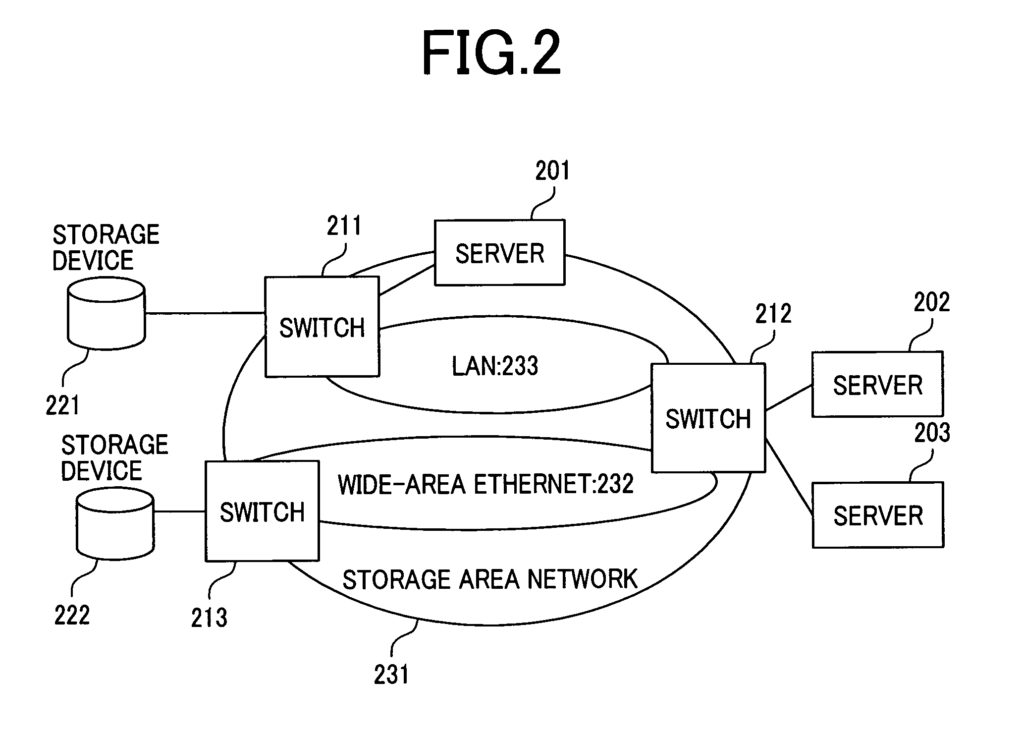
[0050]The first embodiment of this invention is described next while referring to the drawings. The network structure of this invention and the communication method of this invention are described first. An example is described of the case where a computer (server) such as a file server is exchanging file data with a storage device via a storage area network (SAN).

[0051]FIG. 2 is a drawing showing the structure of the storage network utilizing the packet storage device. The storage device and the server are respectively connected by switches. The storage network may at this time include a wide area Ethernet.

[0052]The TCP operation when reading a file on the storage device 221 from the server 201 is described. Since the operation and structure are the same even in protocols other than TCP such as SCTP, the embodiment of this invention is described hereafter using TCP as an example.

[0053]Here, IP addresses are assumed to be assigned to respective communication terminals. In TCP, commu...

second embodiment

[0090]The second embodiment of this invention is described next while referring to the drawings.

[0091]In the second embodiment, an example is described for performing communication between the server 202 and the storage device 222 in a network configuration shown in FIG. 2. The communication protocol utilizes the same structure and operation as the first embodiment even if a protocol other than TCP such as SCTP is used and so TCP is hereafter used as an example in this embodiment of the invention.

[0092]FIG. 6 shows another structure of the TCP transfer control section 101. In addition to the structure of FIG. 1, it contains a protocol change flow identifier table and a protocol converter.

[0093]Compared to the structure of the packet transfer device of the first embodiment, this embodiment possesses the TCP transfer controller of that shown in FIG. 6, for utilizing a UDP capsulizing process to convert packet data between TCP proxy devices.

[0094]When the server 202 has established a T...


PUM


Abstract

A first issue is to provide a packet transfer device for identifying a connection such as a TCP connection linked to a bandwidth control means, and provide a proxy acknowledgment for each identified connection such as TCP. A second issue is to provide a packet transfer device for providing a proxy acknowledgment for a connection such as TCP, and capable of improving throughput such as for TCP just by being installed at a network edge section connected to the communication terminal. As a means to resolve the first issue, a packet transfer device is provided that contains a means for identifying flows such as TCP flows for deciding if the proxy acknowledgment means requires proxy acknowledgment or not, based on the bandwidth conformance flow reported from the bandwidth control means. As a means to resolve the second issue, a packet transfer device is provided that contains a means for converting stored packets to a protocol that does make a proxy acknowledgment, and a means for transmitting the converted packets to a packet transfer device installed on the network edge oriented towards the oncoming packets.

Description

CLAIM OF PRIORITY[0001]The present application claims priority from Japanese application JP 2005-074250 filed on Mar. 16, 2005, the content of which is hereby incorporated by reference into this application.FIELD OF THE INVENTION[0002]The present invention relates to packet transfer devices making up a network and a packet transfer control method for that device, and relates in particular to a packet transfer device and a packet transfer control method utilizing protocol header information for a packet transfer control method conforming with transfer control methods requiring an acknowledgment such as TCP (Transmission Control Protocol) (See non-patent document 1.) SCTP (Stream Control Transmission Protocol) (See non-patent document 5) in transfer control methods for packet transfer devices.BACKGROUND OF THE INVENTION[0003]The application range of networks configured by the Ethernet (Ethernet is a registered commercial trademark.) is expanding and is starting to be applied to storag...

Claims


Application Information

Patent Timeline
Patent Type & Authority Patents(United States)
IPC IPC(8): H04L12/56H04L47/2466
CPCH04L47/10H04L47/193H04L47/20H04L47/2441H04L47/2466H04L47/40H04L69/16H04L69/163
Inventor HIDAKA, MINORUATARASHI, YOSHIFUMI
Owner ALAXALA NETWORKS
Learn More