Metrics and management for flash memory storage life

Active Publication Date: 2010-10-07
HITACHI LTD
View PDF2 Cites 44 Cited by
  • Summary
  • Abstract
  • Description
  • Claims
  • Application Information

AI Technical Summary

Problems solved by technology

This erase operation can cause damage.

Method used


Image

  • Metrics and management for flash memory storage life
  • Metrics and management for flash memory storage life
  • Metrics and management for flash memory storage life

Examples


first embodiment

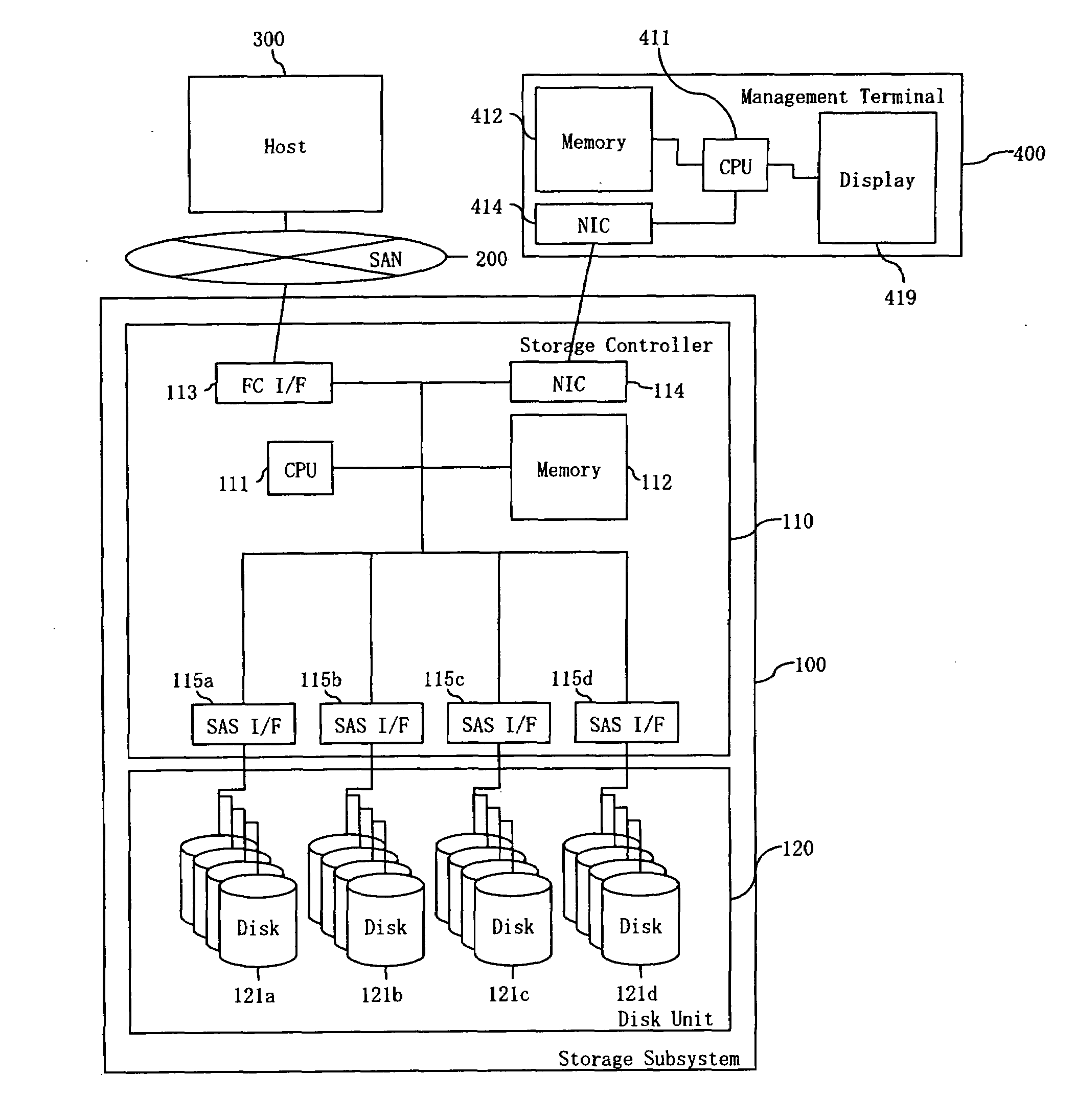
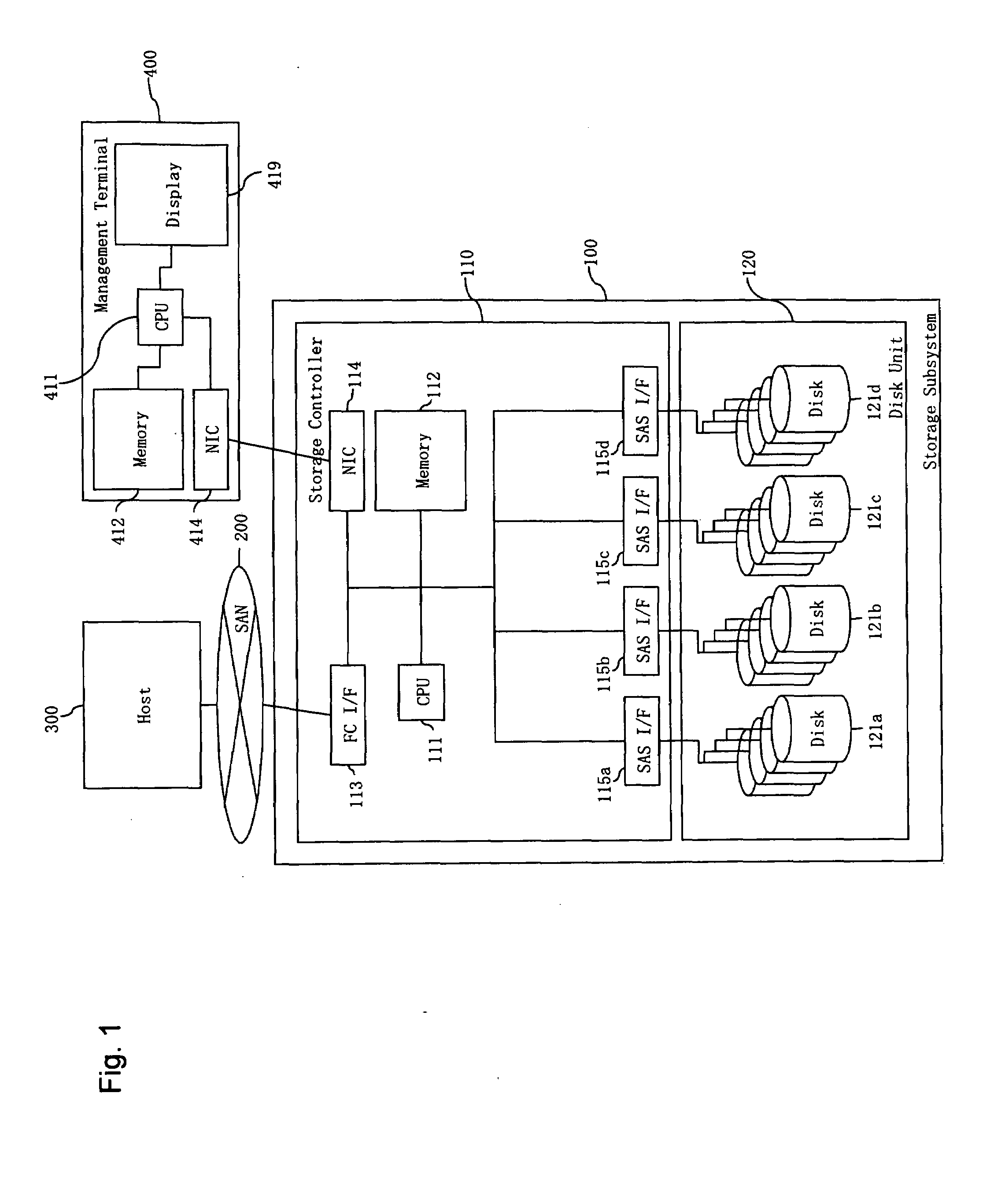
[0088]FIG. 1 illustrates an example of a hardware configuration of a computer system in which the method and apparatus of the invention may be applied. A storage subsystem 100 has a storage controller 110 that includes a CPU 111, a memory 112, a storage interface 113, a local network interface 114, and disk interfaces 115a-115d. The CPU 111 controls the storage subsystem 100, and reads programs and tables from the memory 112. The memory 112 stores the programs and tables. The storage interface 113 connects with a host computer 300 via a storage network 200. The local network interface 114 connects with a storage management terminal 400. The disk interfaces 115a-115d connect with a plurality of disks 121a-121d which are stored in a disk unit 120. The disks 121 include flash memory for storing data. The storage network 200 connects the storage subsystem 100 and the host computer 300. The host computer 300 sends I / O requests to the storage subsystem 100 via the storage network 200, and...

second embodiment

[0118]Only differences between the second embodiment and the first embodiment are described.

[0119]Hardware

[0120]FIG. 23 shows an example of a Disk Management Table 112-11-3′ according to a second embodiment of the invention. Two values are added to the table as compared to FIG. 5. The first is the Life Limit Information 112-11-3′-3 representing the limit number of write times or operations to the disk. This value depends on the flash memory chip type (SLC / MLC), vendor, disk model, capacity (reserved capacity), and wear leveling algorithm. The second is the Life Counter 112-11-3′-4 representing the number of write times to the disk.

[0121]FIG. 24 shows an example of a process flow diagram for the Destaging Control 112-22-2′ according to the second embodiment. One step is added to the table as compared to FIG. 12. In step 112-22-2′-9, the process counts up the Life Counter 112-11-3′-4.

[0122]Expression

[0123]FIG. 25 shows an example of an expression to calculate the reliability at step 1...

third embodiment

[0126]Only differences between the third embodiment and the first embodiment are described.

[0127]Hardware

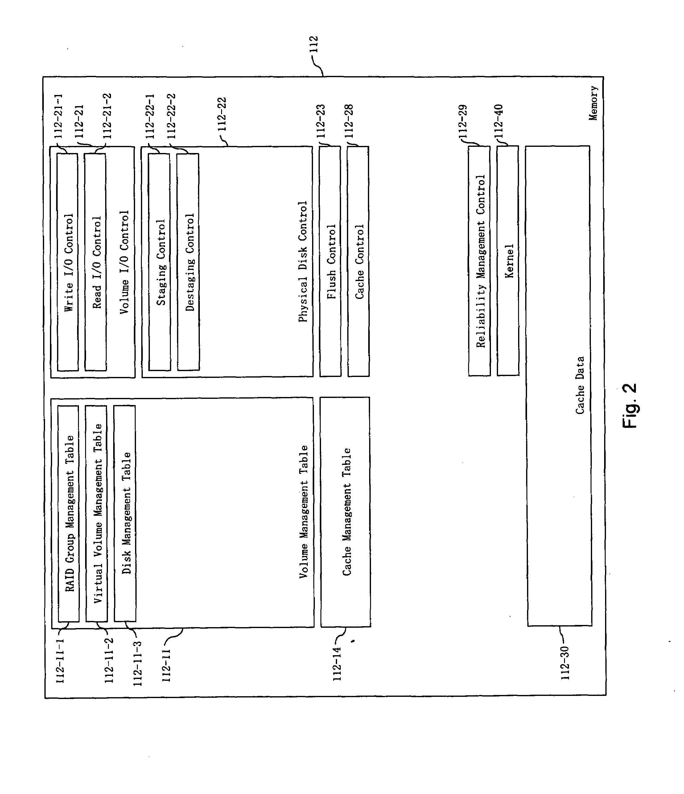
[0128]FIG. 27 shows an example of the memory 112 in the storage subsystem according to a third embodiment of the invention. Four elements are replaced and five elements are added as compared to FIG. 2. The replacing elements are the RAID Group Management Table 112-11-1′, Virtual Volume Management Table 112-11-2′, and Destaging Control 112-22-2′. The added elements are Virtual Volume Page Management Table 112-15-1, Capacity Pool Chunk Management Table 112-15-2, Capacity Pool Page Management Table 112-15-3, Page Migration Control 112-25-1, and the migration control 112-22-3. In the Volume Management Table 112-11, the RAID Group Management Table 112-11-1′ provides physical structure management for the disks 121 and those groups. The Virtual Volume Management Table 112-11-2′ provides volume configuration management. In the added Thin Provisioning Management Table 112-15, the Virtual ...


PUM


Abstract

Embodiments of the invention provide a method and a system for the management of availability and reliability of flash memory media. In one embodiment, a method of evaluating reliability of flash memory media comprises measuring a flash memory remaining life for each disk of a plurality of flash memory media disks provided in one or more flash memory media groups each of which has a configuration, wherein each flash memory media group is one of a RAID group or a thin provisioning pool; obtaining a ratio of sequential to random write I / O types for each flash memory media group; and calculating a remaining life of each flash memory media group based on the measured flash memory remaining life for each disk in said each flash memory media group, the configuration of said each flash memory media group, and the ratio of sequential to random write I / O types for said each flash memory media group.

Description

BACKGROUND OF THE INVENTION[0001]The present invention relates generally to a method and a system for the management of availability and reliability of flash memory media.[0002]For flash memory media, examples of metrics for life time include MTBF (Mean Time Between Failures), MTTF (Mean Time To Failure), and LDE (Long-term Data Endurance). MTBF is a general metric for HDD availability / reliability, and represents a statistic HDD life time. MTTF is a general metric for RAID group availability, and it represents a statistic RAID group life time. LDE is a metric that represents how much capacity the media can be written. An example of storage control for high availability / reliability is RAID (Redundant Array of Independent Disks). RAID 10 has 4 or more disks and stores double data. RAID 5 has 3 or more disks and stores data and parity data. The parity data is generated from the data. This optimized control method is described in U.S. Pat. No. 5,682,396. RAID 6 has 4 or more disks and s...

Claims


Application Information

Patent Timeline
Patent Type & Authority Applications(United States)
IPC IPC(8): G06F12/02G06F12/00
CPCG06F3/0616G06F3/0647G06F3/0653G06F2212/1032G06F12/0246G06F12/0866G06F3/0688
Inventor KAWAGUCHI, TOMOHIRO
Owner HITACHI LTD
Why Eureka
Try Eureka